

Optical lens hole drilling guider
a technology for optical lenses and guide rods, which is applied in the direction of drilling/boring measurement devices, metal working devices, manufacturing tools, etc., can solve the problems of unfavorable movement of bridges, inability to re-use expensive optical lenses, and high manufacturing costs of such rimless spectacles
- Summary
- Abstract
- Description
- Claims
- Application Information
AI Technical Summary
Benefits of technology
Problems solved by technology
Method used
Image

Examples
Embodiment Construction
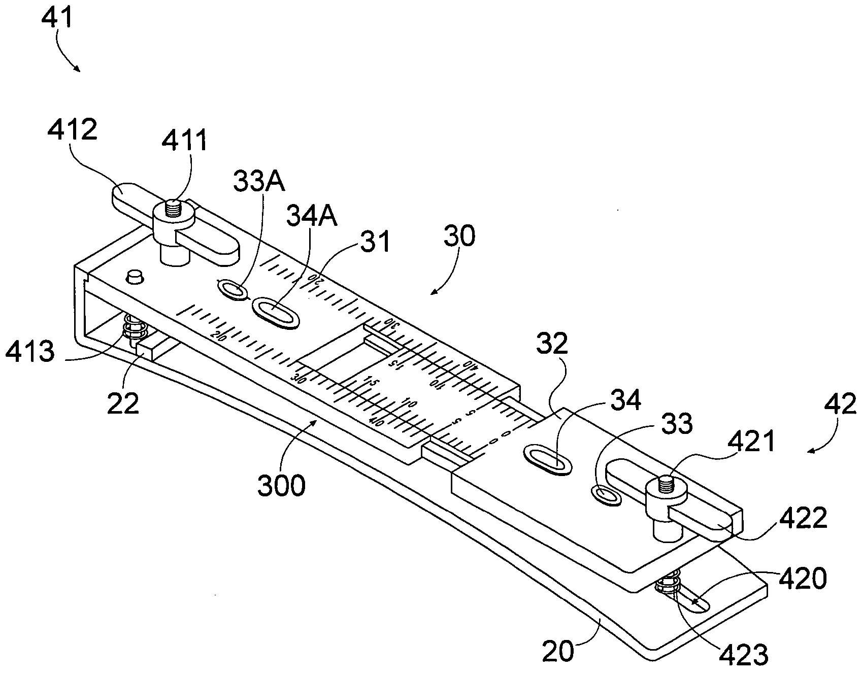
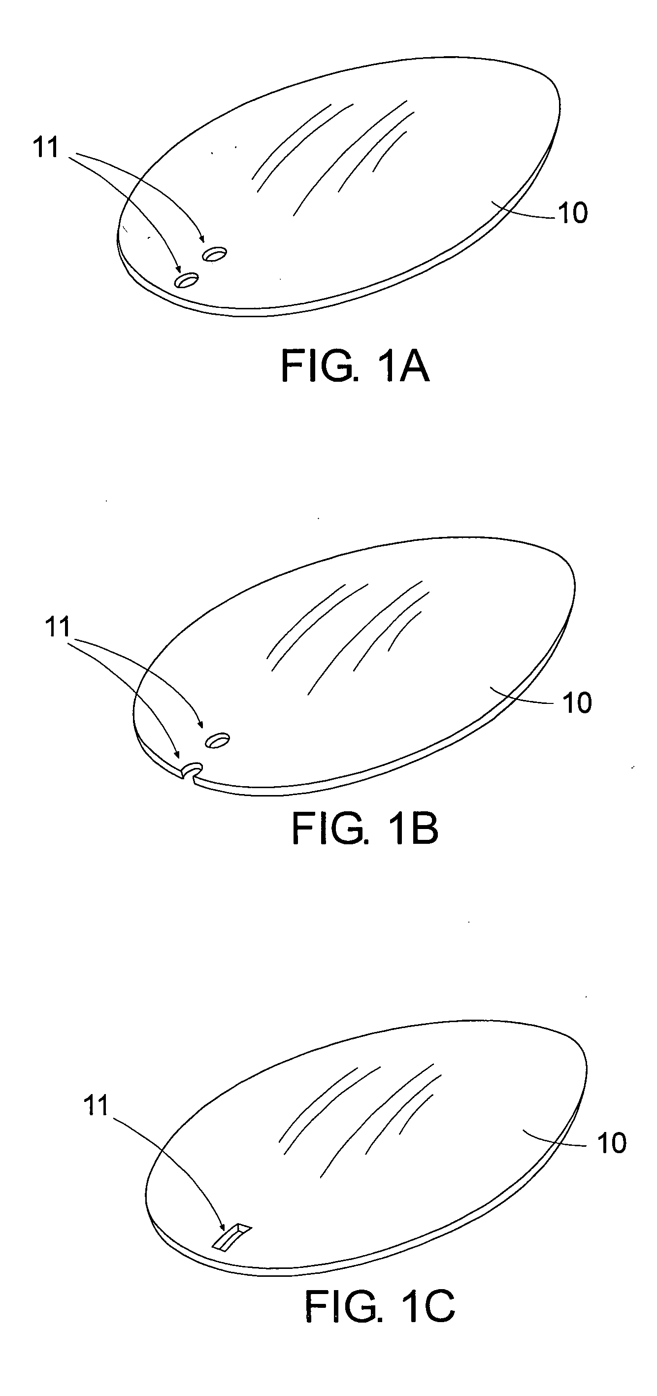
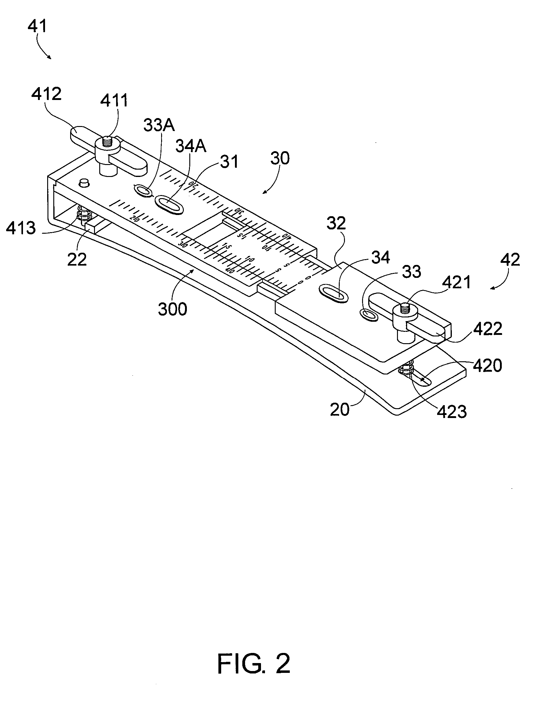
[0024] Referring to FIG. 2 of the drawings, an optical lens hole drilling guider for guiding a though slot 11 formed on an optical lens 10 according to a preferred embodiment of the present invention illustrated, wherein the optical lens hole drilling guider comprises a lower base member 20, an upper guiding member 30, and a retaining device 40.
[0025] The upper guiding member 30 is spacedly overlapped on the base member 20 to form a holding cavity 300 therebetween for holding the optical lens 10 in position, wherein guiding member 30 comprises first and second side guiders 31, 32 slidably mounted to each other in a side-by-side manner such that the second side guider 32 is adapted to sidewardly slide with respect to the first side guider 31 for fitting a width of the optical lens 10. The guiding member 30 further has first and second guiding slots 33, 34 formed on the second side guider 32 to communicate with the holding cavity 300 wherein the first guiding slot 33 is a circular th...
PUM
| Property | Measurement | Unit |
|---|---|---|
| width | aaaaa | aaaaa |
| distance | aaaaa | aaaaa |
| length | aaaaa | aaaaa |
Abstract
Description
Claims
Application Information