Slot array antenna

a technology of array antennas and antennas, applied in the field of slot array antennas, can solve problems such as directivity disorder, and achieve the effects of increasing the reinforcement function, simplifying the assembly, and saving the weight of the radiation portion

Inactive Publication Date: 2005-02-24
TAIYO MUSEN
View PDF5 Cites 10 Cited by
  • Summary
  • Abstract
  • Description
  • Claims
  • Application Information

AI Technical Summary

Benefits of technology

[0022] It is generally desired in the extrusion that thickness is even. In the slot array antenna according to the present invention, the extrusion can be easy because the even thickness can be set in the radiation portion (1) and the reinforcement feeder (2) respectively even if many functions are united in them respectively. Besides, Instability of contact between the slot waveguide (11) and the waveguide holder (12b) as a priority is prevented by uniting the slot waveguide (1a) and the flare holder (1b). Because of being abbreviation structure including the screen holder (1c), overlaps between materials can be little, a flare (3) and a screen (4) can be formed with thin materials or light materials, and further, they may only insert in the assembly, so that saving weight of the radiation portion and simplification of the assembly can be achieved.
[0023] Furthermore, in the case of an open type antenna, because of uniting the reinforcement portion (2b), the feed waveguide (2a) and the reinforcement connector (2c), cooperation of them increases a reinforcement function, so that the materials can be thin and lightened. By uniting the reinforcement portion (2b) and the feed waveguide (2a), the feeder (16) which was necessary separately before is constituted inside the feed waveguide to contribute to simplification. Furthermore, according to unification and simplification, means for securing such as screws and rivets necessary for assembly and connection and secured portions are decreased largely, so that saving weight of the reinforcement feeder and simplification of the assembly can be achieved.
[0024] Thus, according to this invention, the easily assembled slot array antenna in which a number of parts are decreased largely to be lightened and the quality is stable is realized.

Problems solved by technology

However, in the slot array antenna constituted thus, a gap is arisen partially in a contact surface (20) between the slot waveguide (11) and the waveguide holder (12b), so that the adjustment portion (10) does not functioned, as a result, there is possibility such as to disorder the directivity.

Method used


Image

  • Slot array antenna
  • Slot array antenna
  • Slot array antenna

Examples


Embodiment Construction

[0035] Hereinafter, the working mode of a slot array antenna according to the present invention is explained by referring the drawings.

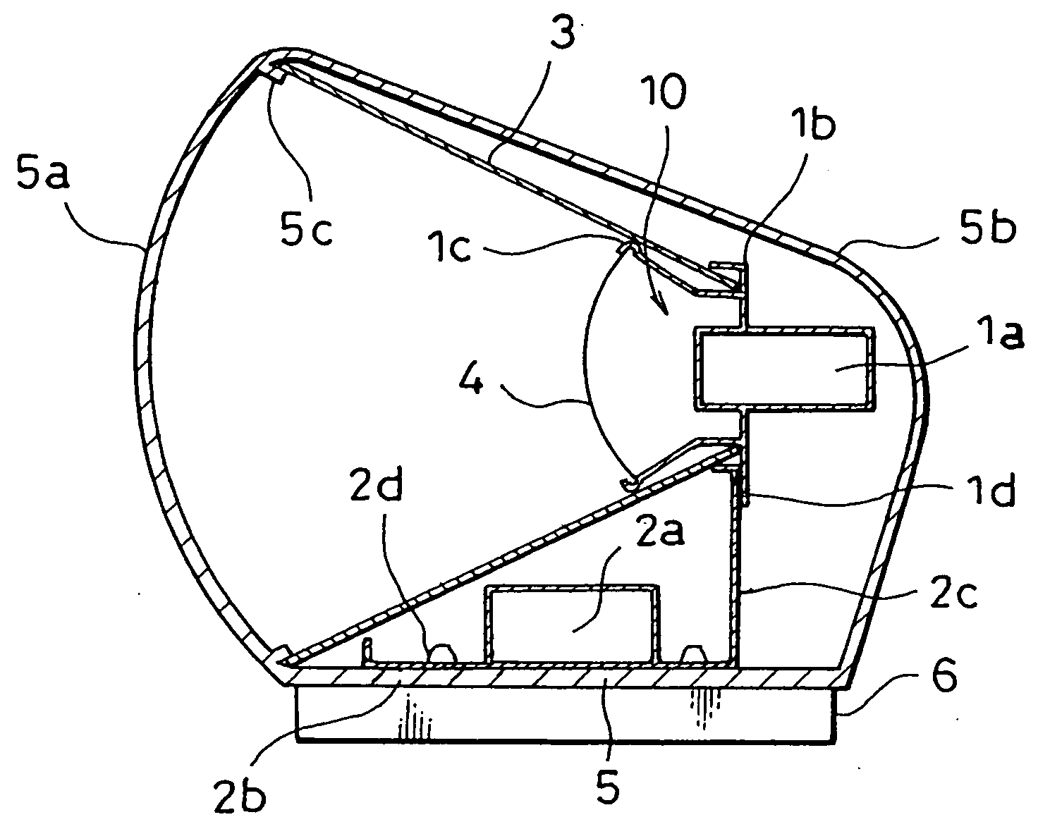
[0036]FIG. 1 is a sectional view of one embodiment of the slot array antenna according to the present invention.

[0037] In this embodiment, a radome radiation portion (5a) and a waterproof box portion (5b) are formed as a unitedly extrusion radome made of ABS resin, and little projections (5c) as a flare support are provided on a boundary line between the radome radiation portion (5a) and the waterproof box portion (5b).

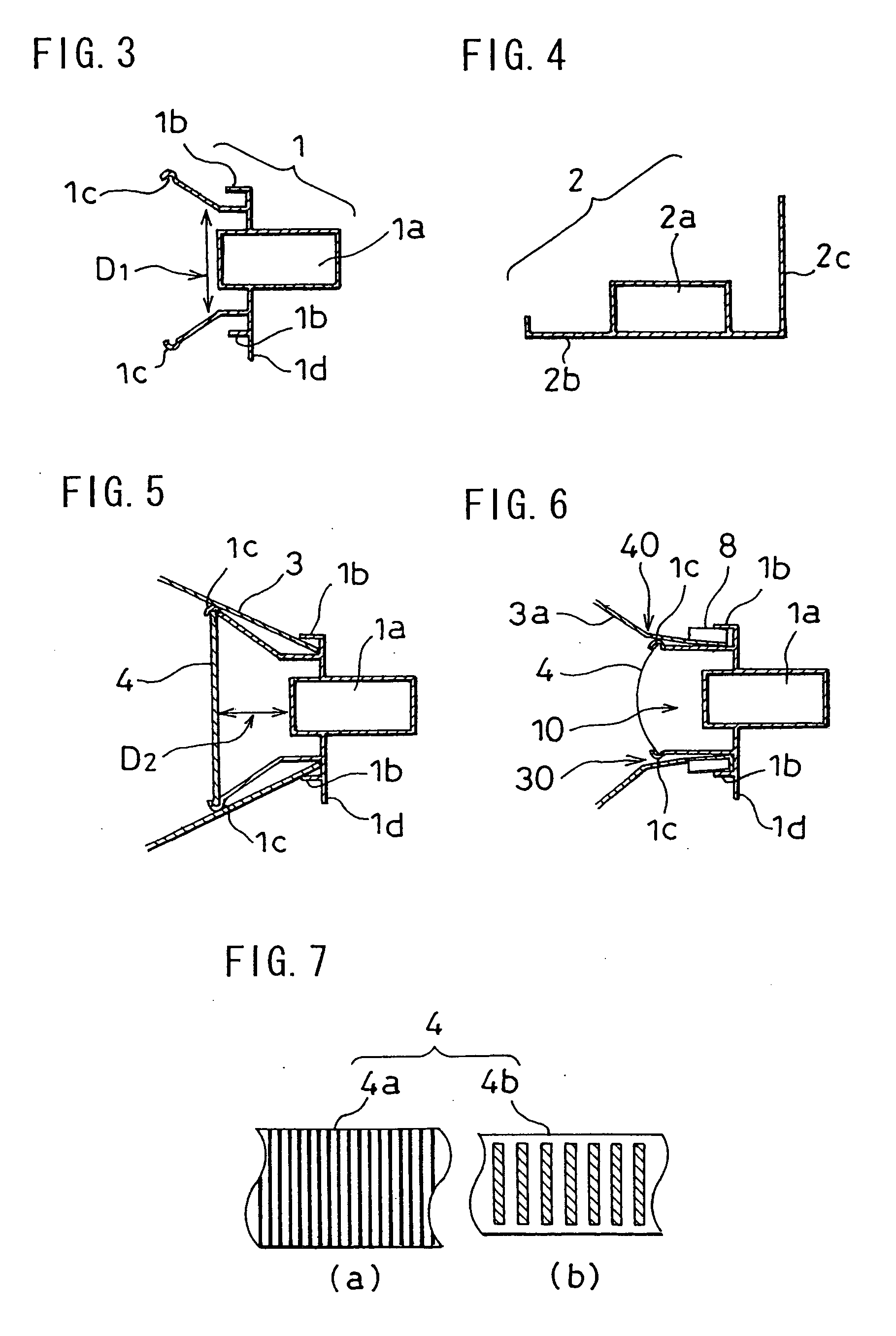
[0038] Furthermore, in this embodiment, a radiation portion (1) is, as shown in FIG. 3, constituted of a slot waveguide (1a), a flare holder (1b), a holder for cross polarization removing screen (1c) and supported portion (1d), and formed unitedly by an aluminum extrusion, etc.

[0039] The slot waveguide (1a) is located horizontally and has a plurality of slots (not shown) which are arranged slantly alternately on an E surface thereo...


PUM


Abstract

An object of the invention is to provide a slot array antenna in which unstable factors for contact of an adjustment portion comprising a slot waveguide and a waveguide holder are removed, a number of parts is decreased to save weight, and assembly is simplification. Accordingly, this invention is to constitute a radiation portion (1) unitedly of a slot waveguide (1a), a flare holder (1b), and a supported portion (1d), if necessary, further adding a screen holder (1c) for a screen (4) for cross polarization suppression. Furthermore, this invention is to constitute a reinforcement feeder (2) unitedly of a feeder waveguide (2a), a reinforcement portion (2b) and a reinforcement connector (2c) in the case of an open type antenna.

Description

BACKGROUND OF THE INVENTION [0001] This invention relates to a slot array antenna which is used mainly in a radar device. [0002] In a radar device such as a radar for vessels, the slot array antenna comprising a waveguide in which the sharp horizontal surface directivity characteristic is gained relatively easily is employed abundantly. [0003]FIG. 2 shows a sectional view of the so-called open type slot array antenna housing only an antenna unit in a waterproofing box (a radome) as one example of a prior slot array antenna. [0004] A slot waveguide (11) shown in FIG. 2 is provided with a plurality of alternately inclined slits (not shown in figures) which constitute an array in an E surface of the waveguide with standard measurement. [0005] A waveguide holder (12b) grasps and fixes the slot waveguide (11), and forms an adjustment portion (10) to adjust to a space of a flare (12a) and to stabilize a level polarization mode. [0006] A screen (13) for cross polarization suppression is to...

Claims


Application Information

Patent Timeline
Patent Type & Authority Applications(United States)
IPC IPC(8): H01P1/02H01P11/00H01Q1/12H01Q1/42H01Q13/02H01Q13/10H01Q13/22H01Q19/185H01Q21/00H01Q21/12
CPCH01Q13/0233H01Q19/185H01Q13/22H01Q21/005
Inventor HIDAI, TAKASHITAMURA, SHINOBU
Owner TAIYO MUSEN
Why Eureka
Try Eureka