Method and system for image processing for structured light profiling of a part

a structured light and image processing technology, applied in the field of structured light profiling of parts, can solve the problems of sampling error, limitation of using laser stripes to obtain accurate profile information, and inability to adequately address sampling error

a structured light and image processing technology, applied in the field of structured light profiling of parts, can solve the problems of sampling error, limitation of using laser stripes to obtain accurate profile information, and inability to adequately address sampling error

US20050046872A1Inactive Publication Date: 2005-03-03GENERAL ELECTRIC CO

Image

  • Method and system for image processing for structured light profiling of a part
  • Method and system for image processing for structured light profiling of a part
  • Method and system for image processing for structured light profiling of a part

Examples


Embodiment Construction

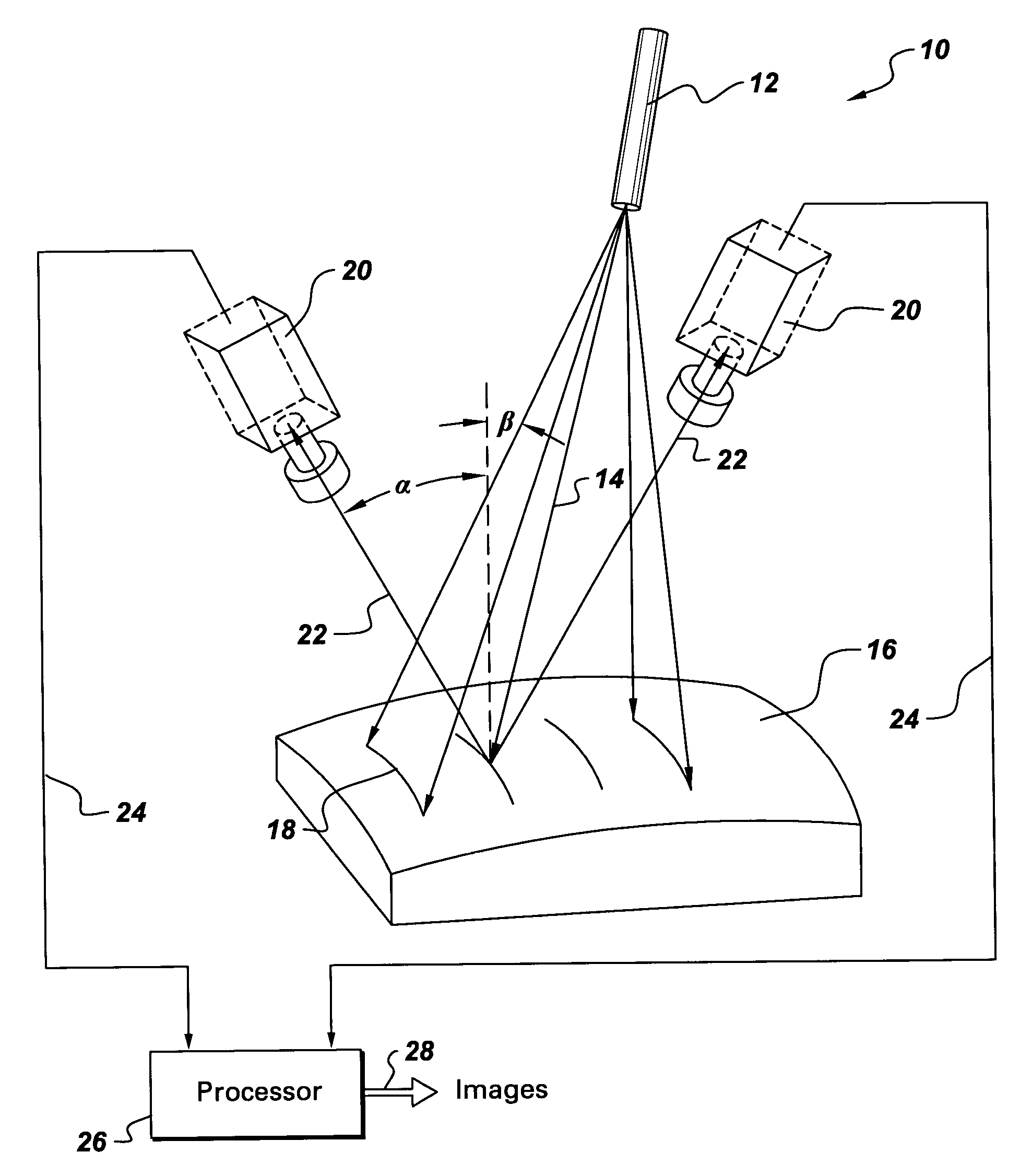
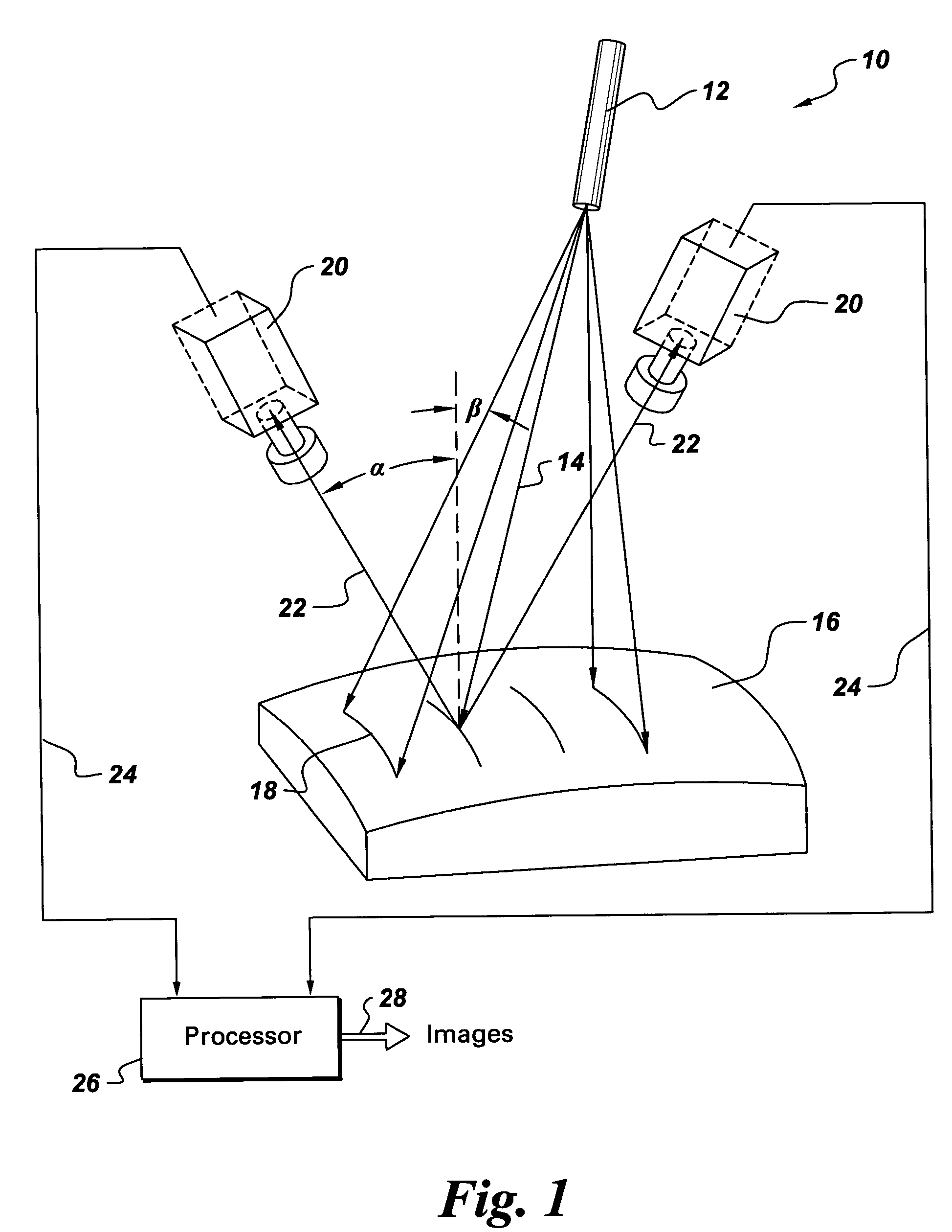
[0017]FIG. 1 illustrates a system 10 for obtaining a three dimensional profile of a part 16 using a structured light pattern 18. The system includes a source 12 of structured light 14 positioned at a predetermined distance from a part. The source 12 projects a beam of structured light 14 to illuminate the part 16. In the illustrated embodiment, a laser is used as the structured light source 14. However other mediums like white light may also be used. At least one imaging device 20 is configured to acquire an image 28 of a structured light pattern of the part 16 by viewing along the direction 22. The imaging device 20 is positioned such that an angle of view (α) of the imaging device 20 is different from an angle of illumination (β) of the source 12. A processor 26 is coupled through 24 to the imaging device 20 and is configured for reconstructing the three dimensional profile of the part using the methods described hereinbelow.

[0018] As would be appreciated by those skilled in the ...


PUM


Abstract

An image processing method for structured light profiling includes sampling an image of a structured light pattern to obtain an intensity distribution, selecting a number of sets of sampled points from the intensity distribution. Each of the respective sets includes a number of sampled points. The image processing method further includes fitting each of the sets of sampled points to a respective distribution function and filtering the distribution functions to select a representative distribution function for the intensity distribution.

Description

BACKGROUND OF THE INVENTION [0001] The present invention relates generally to structured light profiling of a part and more specifically to methods and systems for image processing to obtain a three dimensional profile of a part using a structured light source. [0002] In structured light applications, a three dimensional profile of a part is obtained by using a laser source and at least one video camera. A laser source emanates a laser beam and spreads into multiple (one or more) laser stripes which strikes a surface of a part. These stripes are viewed from one or more video cameras from an angle other than the illumination angle. Typically, applications for structured light profiling include obtaining shape profile information about the part or generating a 3D contour map of the part. [0003] The limitations of using laser stripes to obtain accurate profile information are mainly attributed to sampling error and the noise associated with the laser because the center of a laser strip...

Claims


Application Information

Patent Timeline
03 Mar 2005
Publication
US20050046872A1
IPC
G01B11/24; G01B11/25
CPC
G06T7/0057; G01B11/25; G06T7/521
Inventors
HU, QINGYING; HARDING, KEVIN GEORGE