Adjusting method of image reading apparatus and image reading apparatus

a technology of image reading and reading apparatus, which is applied in the field of image reading apparatus and image reading apparatus adjusting methods, can solve the problems of deteriorating imaging performance, substantial increase in cost, and complicated interior construction of the carriage, and achieves the effect of reducing the size of the focusing correcting means, high quality image information, and high quality image information

Inactive Publication Date: 2005-03-24
CANON KK
View PDF6 Cites 15 Cited by
  • Summary
  • Abstract
  • Description
  • Claims
  • Application Information

AI Technical Summary

Benefits of technology

[0043] According to a first aspect of the present invention, there is used an adjustment chart allowing resolving power evaluation in the sub scanning direction, and the relative positional relationship in the sub scanning direction among a slit portion, an imaging means, and a reading means is adjusted such that light based on an image in the adjustment chart passes the center of the slit and that imaging is effected on the surface of the reading means, thereby making it possible to realize an adjusting method of image reading apparatus and an image reading apparatus which can provide high quality image information.
[0044] According to a second aspect of the present invention, a focusing correcting means is movably mounted in a lens barrel containing the imaging means, whereby it is possible to realize an image reading apparatus which can provide high quality image information and in which it is possible to achieve a reduction in the size of the focusing correcting means, simplify the image reading apparatus assembly process, and protect the lens surface.

Problems solved by technology

However, in these methods, the interior construction of the carriage 88 becomes rather complicated, which involves an exact requirement in terms of assembly accuracy and a substantial increase in cost.
Further, in proportion to the surface precision of the reflecting mirrors and the number of times that reflection is effected, the imaging performance deteriorates, which also affects the read image.
Further, in a carriage-integrated type image reading apparatus, it is rather difficult to maintain high positional accuracy for the parts due, for example, to the large number of components, the great variation in molding accuracy of the carriage in resin molding, which is adopted in view of material cost, etc.
All in all, in a carriage-integrated type image reading apparatus, introduction of an imaging lens (imaging means) with a small imaging area in the sub scanning direction leads to the following problem.
However, in an image reading apparatus having an imaging lens with a rotationally asymmetrical refraction or reflection surface, the imaging area in the sub scanning direction is determined according to the position of the imaging lens 106, so that performing shift adjustment as mentioned above results in the CCD 107 being deviated from the imaging area in the sub scanning direction, making it impossible to obtain satisfactory image information.
However, the apparatus involves the following problems.
For example, in an image reading apparatus using an ultra-wide angle lens as disclosed in U.S. Pat. No. 6,507,444 (Japanese Patent Application Laid-Open No. 2000-171705), the optical path length is small, so that the distance between the imaging lens 117 and the CCD 118 is small, and it is rather difficult to incorporate the focusing correction element 119, with the result that the assembly process is complicated, resulting in a deterioration in process yield and an increase in assembly time.
In particular, with a lens formed by using a cycloolefin polymer type resin or the like, it is impossible to wash away any dirt thereon.

Method used


Image

  • Adjusting method of image reading apparatus and image reading apparatus
  • Adjusting method of image reading apparatus and image reading apparatus
  • Adjusting method of image reading apparatus and image reading apparatus

Examples


embodiment 1

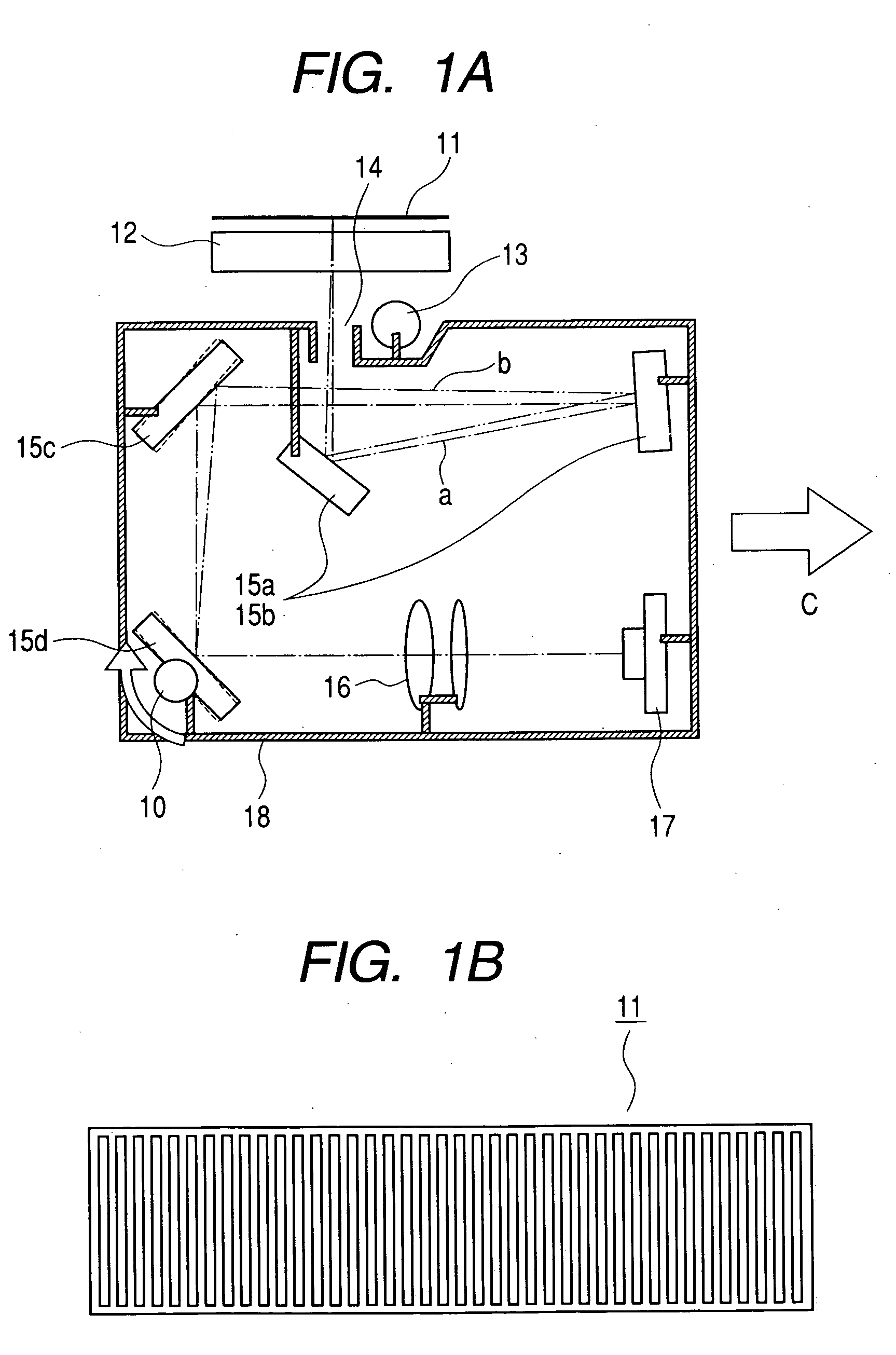
[0062]FIG. 1A is a main portion schematic view of Embodiment 1, illustrating an adjusting method of image reading apparatus according to the present invention; and FIG. 1B is an enlarged explanatory view of an adjustment chart shown in FIG. 1A.

[0063] In the drawings, reference numeral 12 indicates an original table glass, on the surface of which an adjustment chart (multi-line chart) 11 is placed. As shown in FIG. 1B, the adjustment chart has a multi-line portion capable of resolving power evaluation in the sub scanning direction, with the multi-line portion extending in the sub scanning direction.

[0064] Reference numeral 18 indicates a carriage, which retains an illumination light source 13 as a light source means, a slit portion 14, a plurality of reflecting mirrors 15a, 15b, 15c, and 15d, an imaging lens 16 as an imaging means, a photoelectric transducer (CCD) 17 as a reading means, etc., and is adapted to perform scanning in the sub scanning direction by means of a driving dev...

embodiment 2

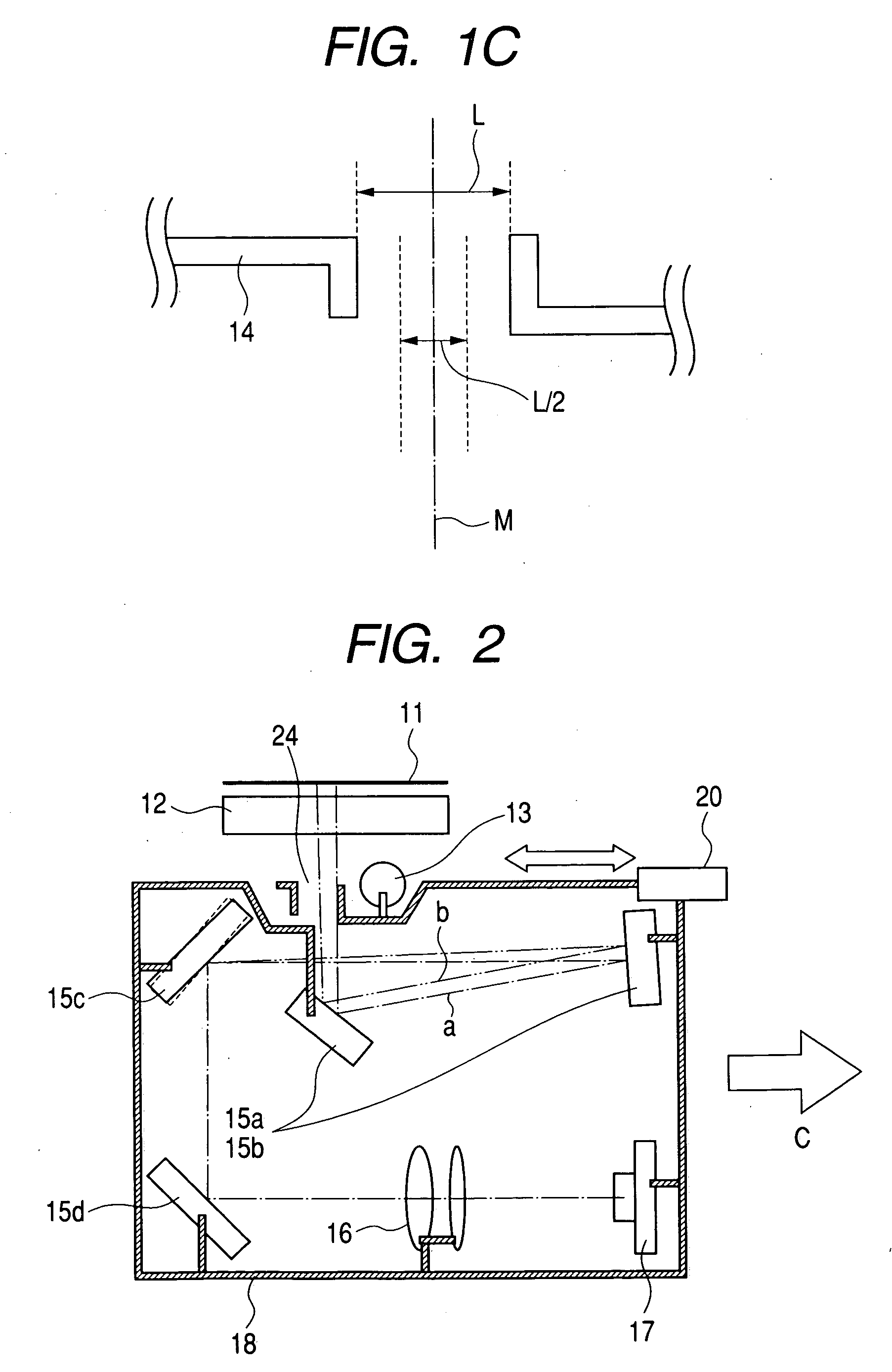
[0080]FIG. 2 is a main portion schematic view illustrating an adjusting method of image reading apparatus according to Embodiment 2 of the present invention. In the drawing, the components that are the same as those shown in FIG. 1A are indicated by the same reference numerals.

[0081] This embodiment differs from Embodiment 1 described above in that the relative positional relationship in the sub scanning direction among the slit portion 24, the imaging lens 16, and the CCD 17 is adjusted by adjusting the position in the sub scanning direction of the slit portion 24. Otherwise, this embodiment is the same as Embodiment 1 in configuration and optical operation, and provides the same effect.

[0082] In the drawing, reference numeral 20 indicates a slit position adjustment device serving as the positioning adjustment means, which is mounted to the slit portion 24, for adjusting the position in the sub scanning direction of the slit portion 24.

[0083] Next, the adjusting method of image ...

embodiment 3

[0091]FIG. 3 is a main portion schematic view illustrating an adjusting method of image reading apparatus according to Embodiment 3 of the present invention. In the drawing, the components that are the same as those shown in FIG. 1A are indicated by the same reference numerals.

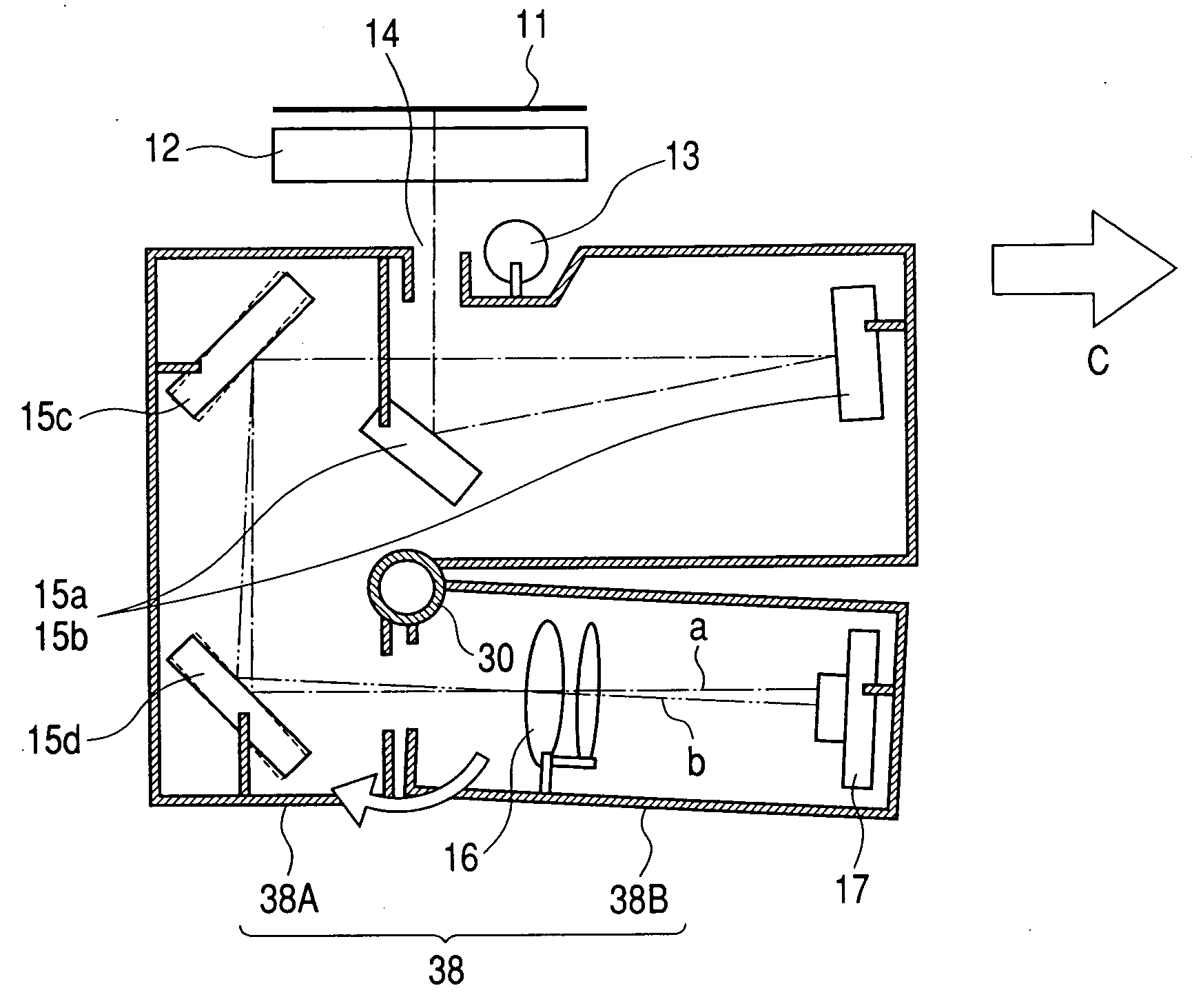
[0092] This embodiment differs from Embodiment 1 described above in that a carriage 38 is composed of a base carriage 38A and a slave carriage 38B, and, by adjusting the relative positional relationship between the two carriages 38A and 38B, the relative positional relationship in the sub scanning direction among the slit portion 14, the imaging lens 16, and the CCD 17 is adjusted. Otherwise, this embodiment is the same as Embodiment 1 in construction and optical operation, and provides the same effect.

[0093] In the drawing, reference numeral 38 indicates the carriage, which includes the base carriage 38a retaining the illumination light source 13, the slit portion 14, and the four reflecting mirrors 15a, 15...


PUM


Abstract

Disclosed is a method of adjusting an image reading apparatus which reads image information of an original by moving relative to the original a carriage retaining a light source, a slit portion, a plurality of mirrors, an imaging device including an optical element with an optical surface rotationally asymmetrical with respect to the optical axis, and a reading device, the method including placing an adjustment chart allowing resolving power evaluation in the sub scanning direction on an original table glass, illuminating the adjustment chart by the light source, and adjusting, by using an image of the adjustment chart thus illuminated, the relative positional relationship in the sub scanning direction among the slit portion, the imaging device, and the reading device by a positioning adjustment device such that imaging of the light beam passing through a slit center of the slit portion is effected on the surface of the reading device. By performing information through adjustment using the adjustment chart, there are provided an adjusting method of image reading apparatus and an image reading apparatus which provide high quality image.

Description

BACKGROUND OF THE INVENTION [0001] 1. Field of the Invention [0002] The present invention relates to an adjusting method of image reading apparatus and an image reading apparatus, in particular, those suitable for use in and as an image reading apparatus, such as an image scanner, a copying machine, and a facsimile apparatus, in which image information of an original is imaged on the surface of a reading means (CCD), making it possible to perform image reading with high accuracy. [0003] 2. Related Background Art [0004]FIG. 8 is a schematic view of a main portion of a conventional carriage-integrated type image reading apparatus (flat head scanner). [0005] In the drawing, reference numeral 82 indicates an original table glass, on which an original 81 is placed. Reference numeral 88 indicates a carriage, which retains an illumination light source 83 described below, a plurality of reflecting mirrors 85a, 85b, 85c, and 85d, an imaging lens 86, a reading means 87, etc., and performs sca...

Claims


Application Information

Patent Timeline
Patent Type & Authority Applications(United States)
IPC IPC(8): G02B17/00G03B27/50G02B26/10H04N1/028H04N1/04H04N1/10H04N1/107H04N1/19
CPCH04N1/00002H04N1/00013H04N2201/04755H04N1/00031H04N1/00045H04N1/00063H04N1/00087H04N1/03H04N1/0305H04N1/0473H04N2201/02416H04N2201/0242H04N2201/02429H04N2201/02431H04N2201/02433H04N2201/02495H04N2201/0471H04N2201/04717
Inventor HAYASHIDE, TADAO
Owner CANON KK
Why Eureka
Try Eureka