
Endoscope system

a technology of endoscope and endoscope, which is applied in the field of endoscope system, can solve the problems of affecting the appearance of noise in the displayed image, limiting the number of bits that can be corrected, and unavoidably degrading the image, and achieves the effect of high quality

Inactive Publication Date: 2011-12-08
FUJIFILM CORP
View PDF12 Cites 35 Cited by
  • Summary
  • Abstract
  • Description
  • Claims
  • Application Information

AI Technical Summary

Benefits of technology

The invention is an endoscope system that can capture high quality images even if there is noise in the image during transmission. The system includes an endoscope with a camera that captures images and a controller that receives the images through a signal line. The endoscope has multiple light receiving portions arranged in a two-dimensional pattern and a driving part that reads the charge signals from the light receiving portions. The driving part conducts a read scan of the charge signals from each light receiving portion along a main scanning direction and a perpendicular sub scanning direction. The driving part then changes the order in which the lines of the image data are output by conducting the read scan on all lines in the captured image. This results in a high quality image output that is not affected by noise during transmission.

Problems solved by technology

Furthermore, although noise may be eliminated through error correction by adding an error check code to every prescribed data in the serial data transmission, there is a limit to bits that can be corrected for errors, and if a burst error occurs, it cannot be corrected, and hence the image is unavoidably degraded.
Therefore, even when a captured image signal is serially transmitted to the controller from the endoscope for reducing the degradation in the image quality, when noise externally influences during the transmission, the influence of the noise conspicuously appears in a displayed image.

Method used


Image

  • Endoscope system
  • Endoscope system
  • Endoscope system

Examples


Embodiment Construction

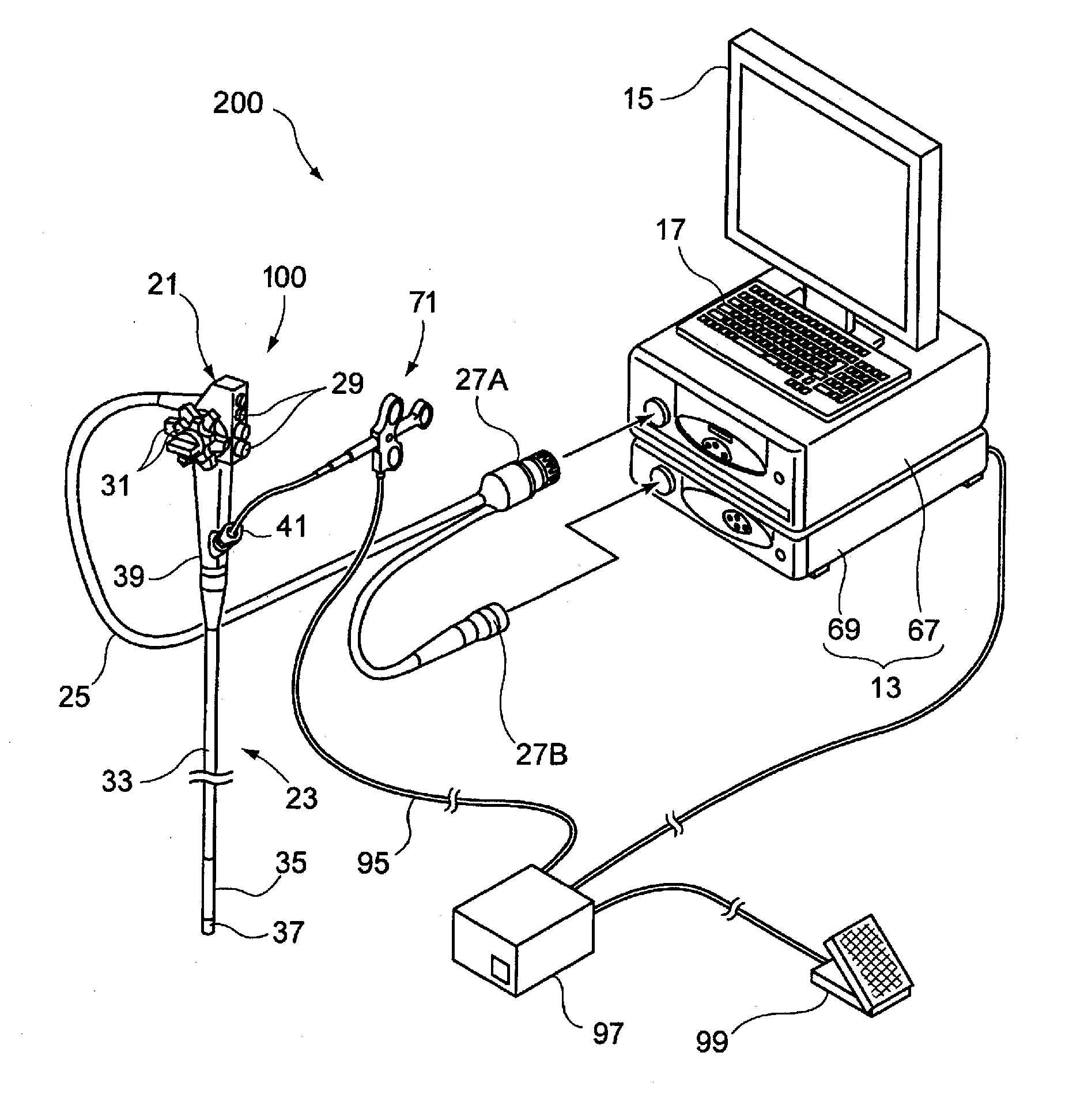
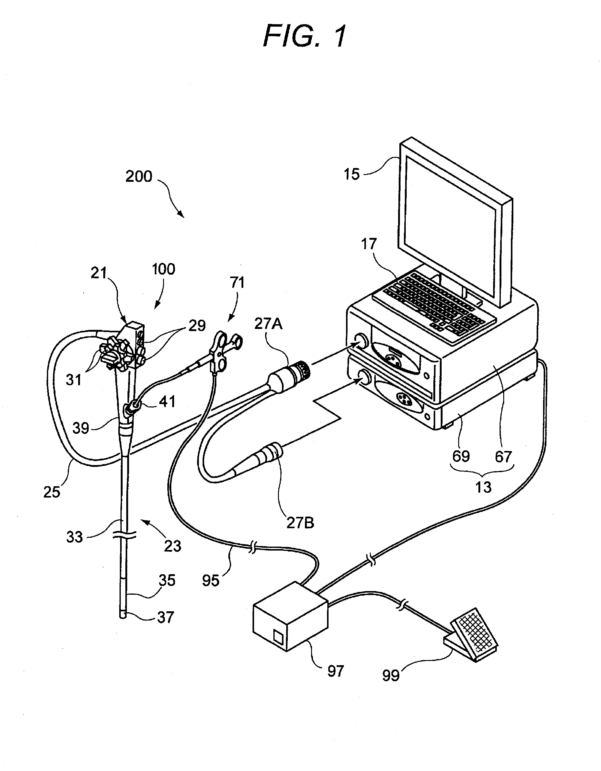
[0031]Now, a preferred embodiment of the invention will be described in detail with reference to the accompanying drawings.

[0032]FIG. 1 is a schematic diagram illustrating the whole structure of an endoscope system including an endoscopic device for explaining the embodiment of the invention.

[0033]The endoscope system 200 includes the endoscopic device (hereinafter sometimes referred to as the endoscope) 100, a controller 13 connected to the endoscope 100, a display section 15 such as a monitor, an input section 17 such as a keyboard, a treatment instrument 71, a high frequency power control section 97 for driving the treatment instrument 71, and a foot switch 99 connected to the high frequency power control section 97. The controller 13 includes a light source section 67 for supplying the endoscope 100 with illumination light and a processor section 69 for subjecting an imaging signal supplied from the endoscope 100 to various image processing for converting it into a video signal....


PUM


Abstract

An endoscope system includes an endoscope including an imaging part and a controller separated from the endoscope and connected to the endoscope through a signal line. The imaging part includes a plurality of light receiving portions two-dimensionally arranged and a driving part that reads a charge signal stored in each of the light receiving portions. The driving part conducts read scan in which read of the charge signals from the light receiving portions in a main and sub scanning direction. The driving part changes an order of outputting the lines in the image data by conducting the read scan on all lines included in the captured image so as to scan some lines successively with a prescribed number of lines interlaced along the sub scanning direction and scan the other lines successively from an interlaced line with the prescribed number of lines interlaced.

Description

[0001]The present application claims priority from Japanese Patent Application No. 2010-130220 filed on Jun. 7, 2010, the entire content of which is incorporated herein by reference.BACKGROUND OF INVENTION[0002]1. Field of the Invention[0003]The present invention relates to an endoscope system.[0004]2. Description of the Related Art[0005]As a technology for signal transmission of a captured image between an endoscope and a controller connected to the endoscope, a system employing analog transmission is described in JP-A-60-55923. In this system, a noise elimination device generates positive and negative video signals on the basis of image information of a captured image and these video signals are synchronized with each other and transmitted to the controller, so that degradation in the image quality may be restored by utilizing the symmetry between these video signals. Thus, image information may be transmitted with high noise resistance and without causing a large failure in the i...

Claims


Application Information

Patent Timeline
Patent Type & Authority Applications(United States)
IPC IPC(8): H04N7/18H04N25/00H04N25/42
CPCA61B1/00009A61B1/00018A61B1/00039A61B1/00045A61B1/0051A61B1/0052H04N2005/2255A61B1/05A61B18/1492A61B2018/1475H04L25/4908H04N5/343H04N5/3532A61B1/018A61B1/000095H04N23/555H04N25/42H04N25/531
Inventor MURAKAMI, HIROSHI
Owner FUJIFILM CORP
Learn More