Multi-piece front loading liner

a front loading liner and multi-piece technology, applied in the field of liners, can solve the problems of operator injury and time-consuming process

Active Publication Date: 2005-04-07
ILLINOIS TOOL WORKS INC
View PDF11 Cites 24 Cited by
  • Summary
  • Abstract
  • Description
  • Claims
  • Application Information

AI Technical Summary

Benefits of technology

[0007] Embodiments of this aspect of the invention can include one or more of the following features. A proximal end portion of the liner retainer can be adapted to receive the liner insert. A distal end portion of the liner retainer can include a screw thread for securing the liner retainer to the torch. The distal end portion of the liner retainer can further include a sealing member (e.g., an o-ring, a polymer seal, a grommet) that substantially prevents a shielding gas from leaking from the distal end of the torch. In embodiments, the distal end portion of the liner retainer defines an aperture sized to allow an electrode wire to pass through.
[0008] In certain embodiments, the distal end portion of the liner insert includes an element (e.g., a screw

Problems solved by technology

This step necessitates that the weld operator move around the welding apparatus (e.g., torch and robotic arm), which requires care

Method used


Image

  • Multi-piece front loading liner
  • Multi-piece front loading liner
  • Multi-piece front loading liner

Examples


Embodiment Construction

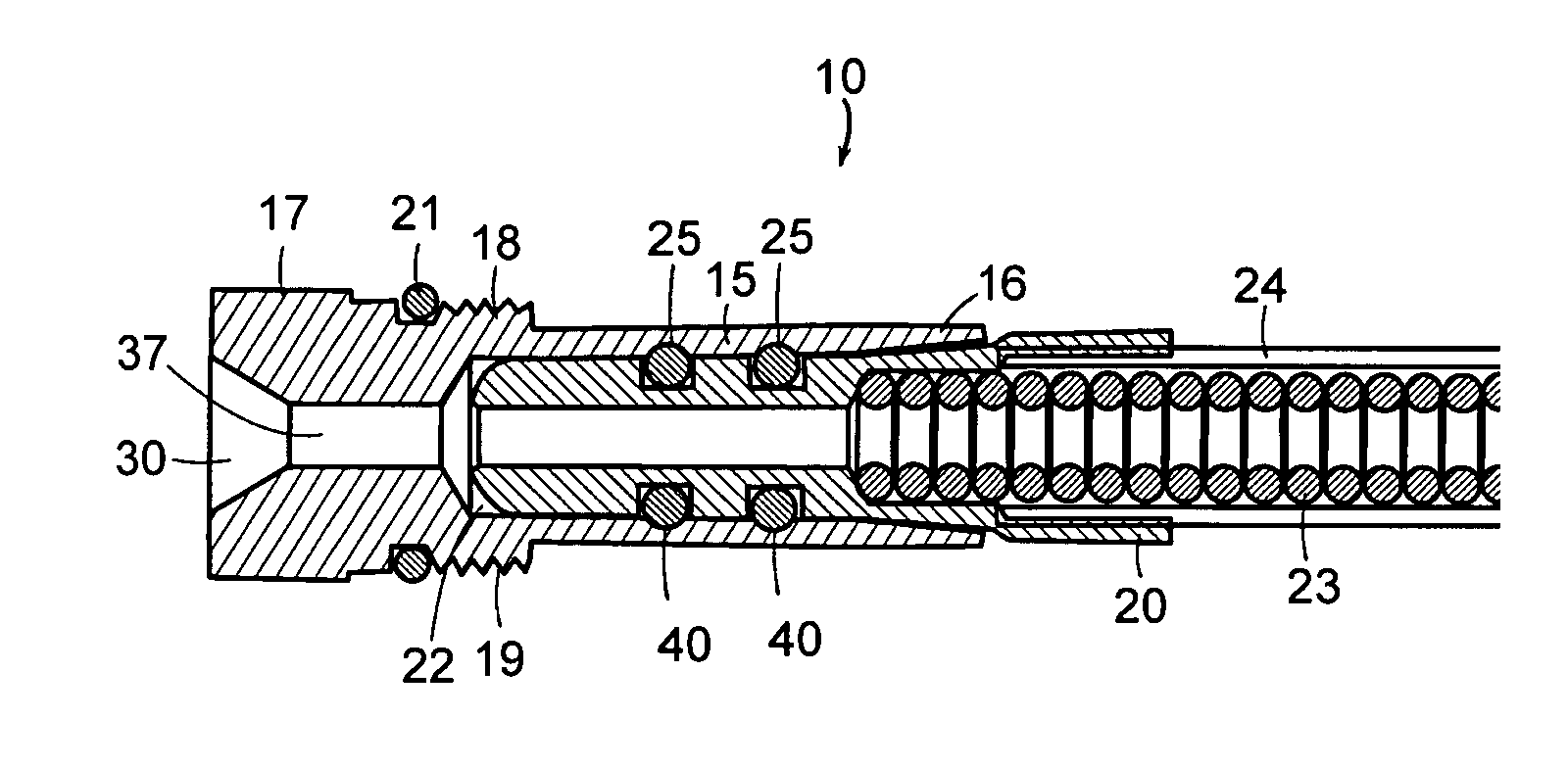
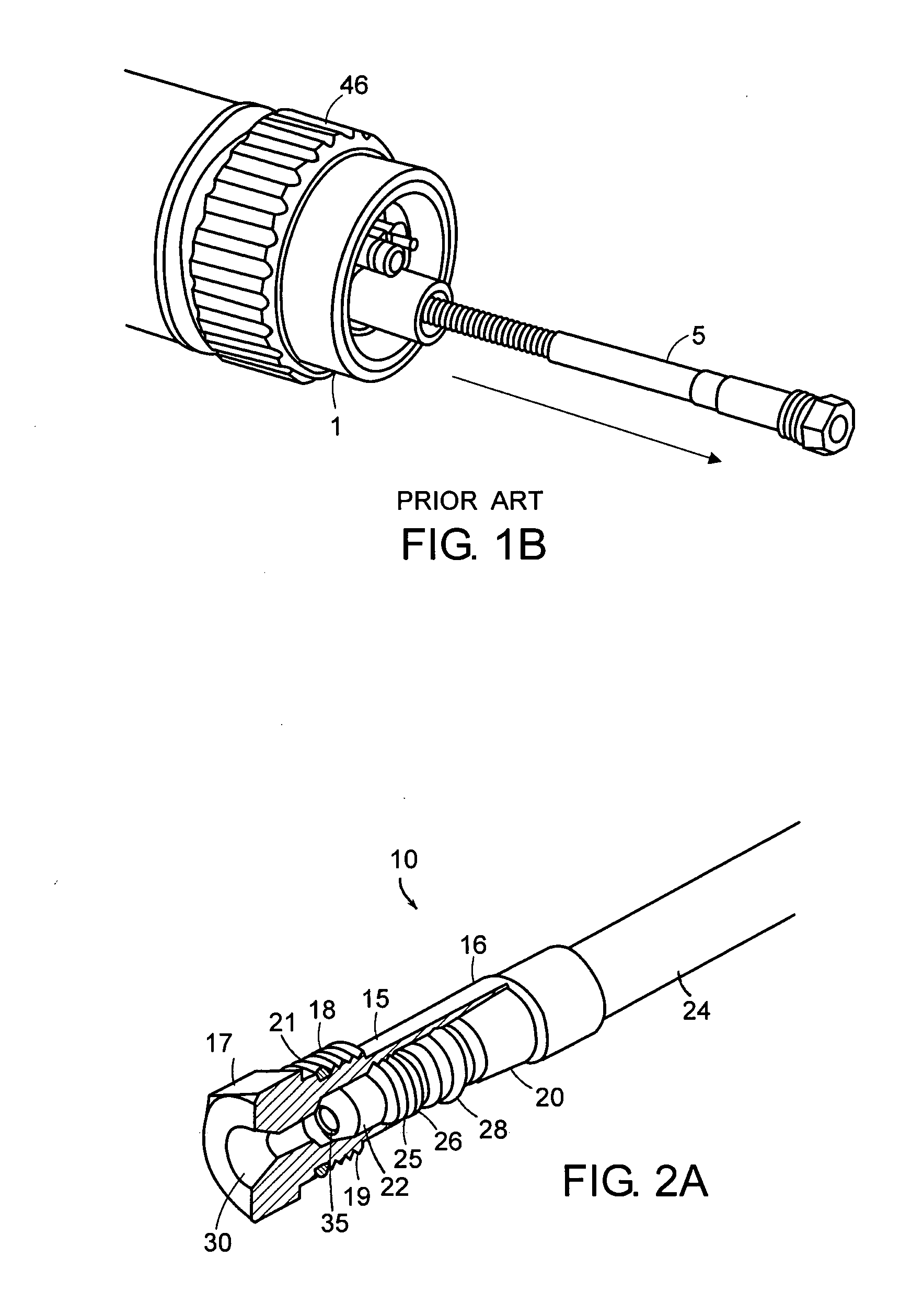
[0024] The present invention provides an apparatus and method for installing, removing, and replacing a consumable portion of a liner from a proximal end of a welding torch. In some embodiments, the liner includes multiple pieces, such as, for example, a liner retainer and a liner insert. The liner retainer is inserted into a welding torch and is removably coupled to the welding torch's distal end. The liner insert is a tubular device, which is removably coupled to the liner retainer (e.g., a distal end of the liner insert is removably coupled to a proximal end of the liner retainer). When decoupled from the liner retainer, the liner insert can be inserted into and removed out from the proximal end of the welding torch. In general, the liner of the present invention is easier to install and less time-consuming to remove and replace than conventional liners. Moreover, the likelihood of operator injury during maintenance is decreased because the welding torch operator does not have to...


PUM

PropertyMeasurementUnit
Lengthaaaaaaaaaa
Forceaaaaaaaaaa

Abstract

An improved liner for protecting an electrode wire within a body of a welding torch. The liner includes a liner retainer, which is removably coupled to a liner insert. The liner retainer is secured to a distal end of the welding torch and the liner insert is inserted and coupled to the liner retainer through a proximal end of the welding torch.

Description

RELATED APPLICATIONS [0001] This application claims priority to U.S. provisional application Ser. No. 60 / 499,263, filed on Aug. 29, 2003, and entitled “Two Piece Front Loading Liner.”FIELD OF THE INVENTION [0002] The invention generally relates to liners used in welding torches. In particular, the invention relates to an improved liner and methods of installation and removal of the improved liner in Gas Metal Arc Welding (GMAW) torches, Metal Inert Gas (MIG) torches, and Flux Core Arc Welding (FCAW) torches. BACKGROUND OF THE INVENTION [0003] GMAW and MIG torches are widely used to weld metallic materials. Referring to FIG. 1A, a GMAW or MIG torch 1 generally includes a torch body 2, a wire electrode that is fed through the torch body by a wire feeder 3, a nozzle 4, a gas diffuser, electrical connections and a power supply. A contact tip provides a point of electrical contact enabling the welding current to pass into the electrode wire as it feeds through the contact tip. When the w...

Claims


Application Information

Patent Timeline
IPC IPC(8): B23K9/12B23K9/133B23K37/02
CPCB23K9/122B23K9/133B23K9/32B23K9/295B23K9/287
Inventor LAJOIE, ROBERT
Owner ILLINOIS TOOL WORKS INC
Why Eureka
Try Eureka