Cervical-thoracic-lumbar spine phased array coil for Magnetic Resonance Imaging

a phased array coil and cervical spine technology, applied in the field of medical imaging systems, can solve the problems of coil not providing the best snr in the spine region, the structure is not suitable for spine imaging, and the axial and coronal imaging has a shading problem

Active Publication Date: 2005-06-09
GENERAL ELECTRIC CO
View PDF17 Cites 4 Cited by
  • Summary
  • Abstract
  • Description
  • Claims
  • Application Information

AI Technical Summary

Problems solved by technology

The first application of such a phased array design was intended for the spine region because the required coverage of the spine area for the human body is extremely large and a single receive coil structure could not adequately provide the image necessary for clinical evaluation.
The use of these phased array coil structures, for example, a row of square loop coils for spine scanning when the coils are lined up in the head-foot (HF) direction, results in a shading problem with axial and coronal imaging.
Thus, if the left-right center of this phased array is positioned to the center of the spine, the coil does not provide the best SNR in the spine region because the coil sensitivity tilts to one side.
This structure is not suitable for spine imaging.
This triangle shape array is not suitable to make a spine coil with several coil sections in the HF direction.
Wh...

Method used


Image

  • Cervical-thoracic-lumbar spine phased array coil for Magnetic Resonance Imaging
  • Cervical-thoracic-lumbar spine phased array coil for Magnetic Resonance Imaging
  • Cervical-thoracic-lumbar spine phased array coil for Magnetic Resonance Imaging

Examples


Embodiment Construction

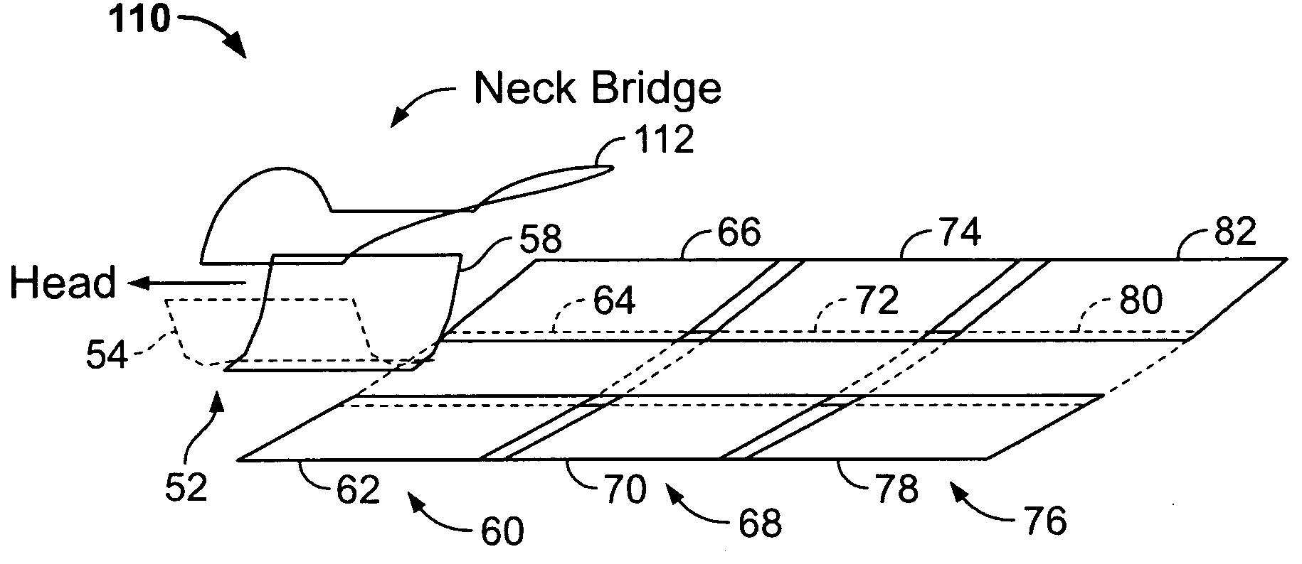
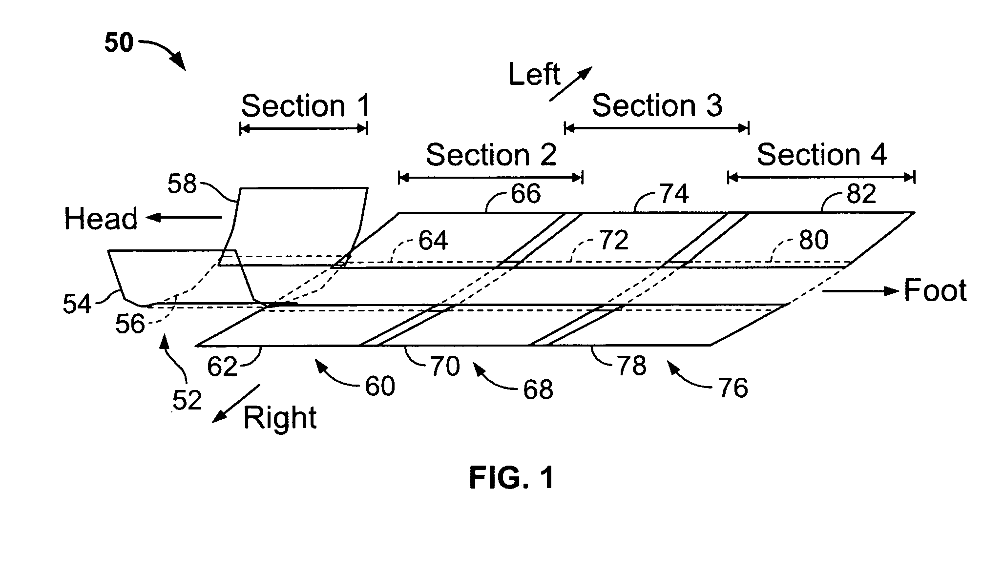
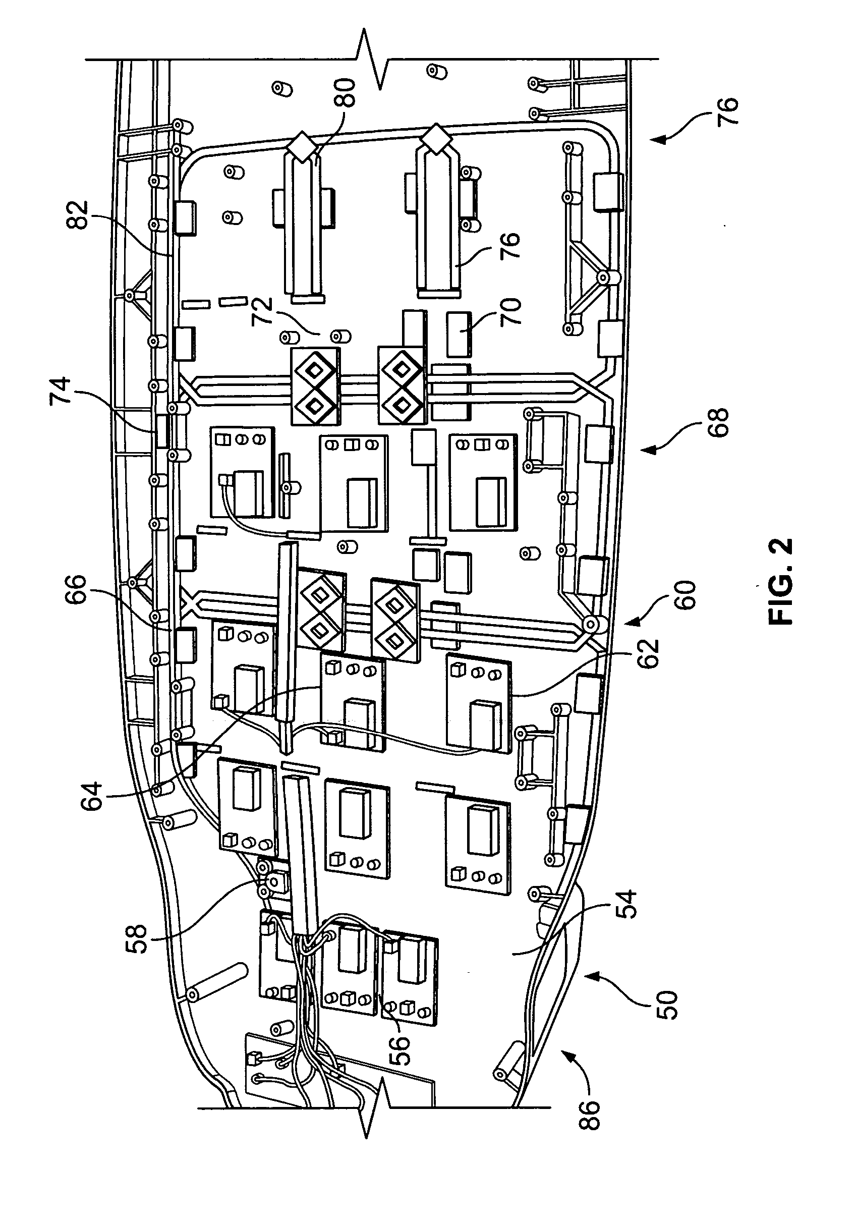
[0026] Various embodiments of the present invention provide a phased array coil for imaging, for example, the Cervical-Thoracic-Lumbar (CTL) spine of the human body using a Magnetic Resonance Imaging (MRI) system. The various embodiments may be used in a horizontal MRI system with, for example, a 3-Telsa (3T) main magnetic field strength. However, the various embodiments may be used in MRI systems having a lower or greater main magnetic field strength. Due to the human body's dielectric and conductive effect on the high frequency electromagnetic field, an RF coil with a symmetrical structure receives asymmetrical signals from the body. This causes, for example, spine images made by a traditional CTL coil, which has a symmetrical quadrature pair structure, to have left-right (LR) shading. Various embodiments of the invention provide a three-loop coil structure to provide a wide uniform sensitivity area with a high SNR in the LR direction to cover the spine and nearby tissue regardles...


PUM


Abstract

A phased array coil for a Magnetic Resonance Imaging (MRI) system is provided that includes a first coil, a second coil adjacent the first coil, and a third coil adjacent the second coil. The first, second and third coils are configured in a parallel arrangement in a left-right direction of the MRI system.

Description

CROSS REFERENCE TO RELATED APPLICATIONS [0001] This application claims priority to and the benefit of the filing date of U.S. Provisional Application No. 60 / 523,657, filed on Nov. 19, 2003 and which is hereby incorporated by reference in its entirety.BACKGROUND OF THE INVENTION [0002] This invention relates generally to medical imaging systems, and more particularly, to a phased array coil for a Magnetic Resonance Imaging (MRI) system. [0003] MRI or Nuclear Magnetic Resonance (NMR) imaging generally provides for the spatial discrimination of resonant interactions between Radio Frequency (RF) waves and nuclei in a magnetic field. NMR signals are typically detected using a receive RF coil, which is placed in the vicinity of a volume excited by the magnet system of the MRI or NMR scanner. [0004] It is known to use a phased array configuration for RF coils in MRI to receive NMR signals. For example, a phased array surface coil for horizontal field MRI systems may include a surface phase...

Claims


Application Information

Patent Timeline
IPC IPC(8): G01R33/3415
CPCG01R33/3415
Inventor FENG, LIMINLAKSHMANAN, KARTHIKCHEN, VINCENT W.SLADKEY, JACOB L.
Owner GENERAL ELECTRIC CO
Why Eureka
Try Eureka