Frequency conversion in a receiver

a receiver and frequency technology, applied in the field of frequency conversion, can solve the problems of large power consumption, low signal-to-noise ratio, and low distortion of the first mixer, and achieve the effects of fewer elements, low power consumption, and high signal-to-noise ratio

Inactive Publication Date: 2005-07-28
QUANTEK
View PDF14 Cites 26 Cited by
  • Summary
  • Abstract
  • Description
  • Claims
  • Application Information

AI Technical Summary

Benefits of technology

[0012] The object of the present invention is to provide a TV tuner with fewer elements, a lower power consumption and high signal-to-noise ratio.

Problems solved by technology

This approach leads to minimum distortion due to mixer images and harmonic mixing.
In the previously described TV tuner, however, the out-of-band channels must be removed by an external RF SAW (surface acoustic wave) filter, which necessitates a highly linear SAW driver requiring a large power consumption in the tuner chip.
Further, the PLL (phase lock loop) circuit to generate the oscillation signal for the first mixer operates at a high frequency, which results in a spurious output of the first mixer.

Method used


Image

  • Frequency conversion in a receiver
  • Frequency conversion in a receiver
  • Frequency conversion in a receiver

Examples


Embodiment Construction

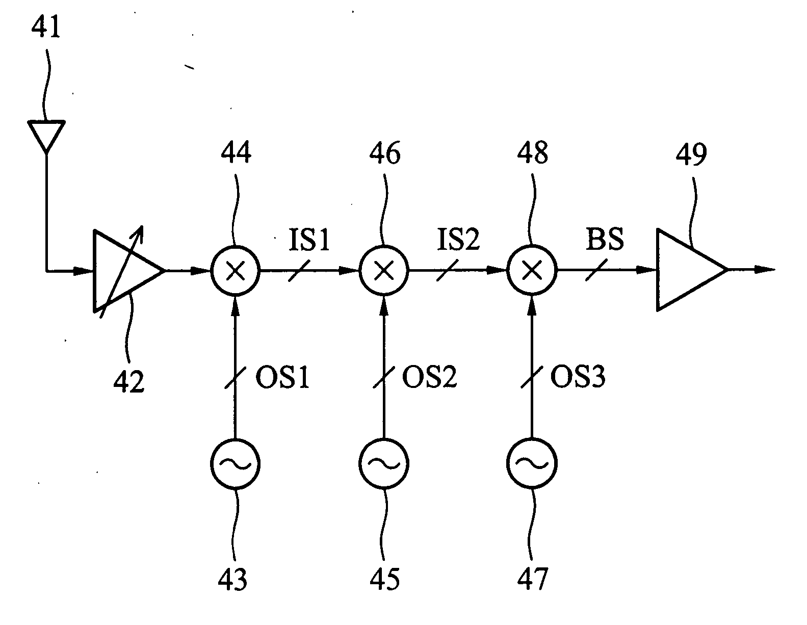
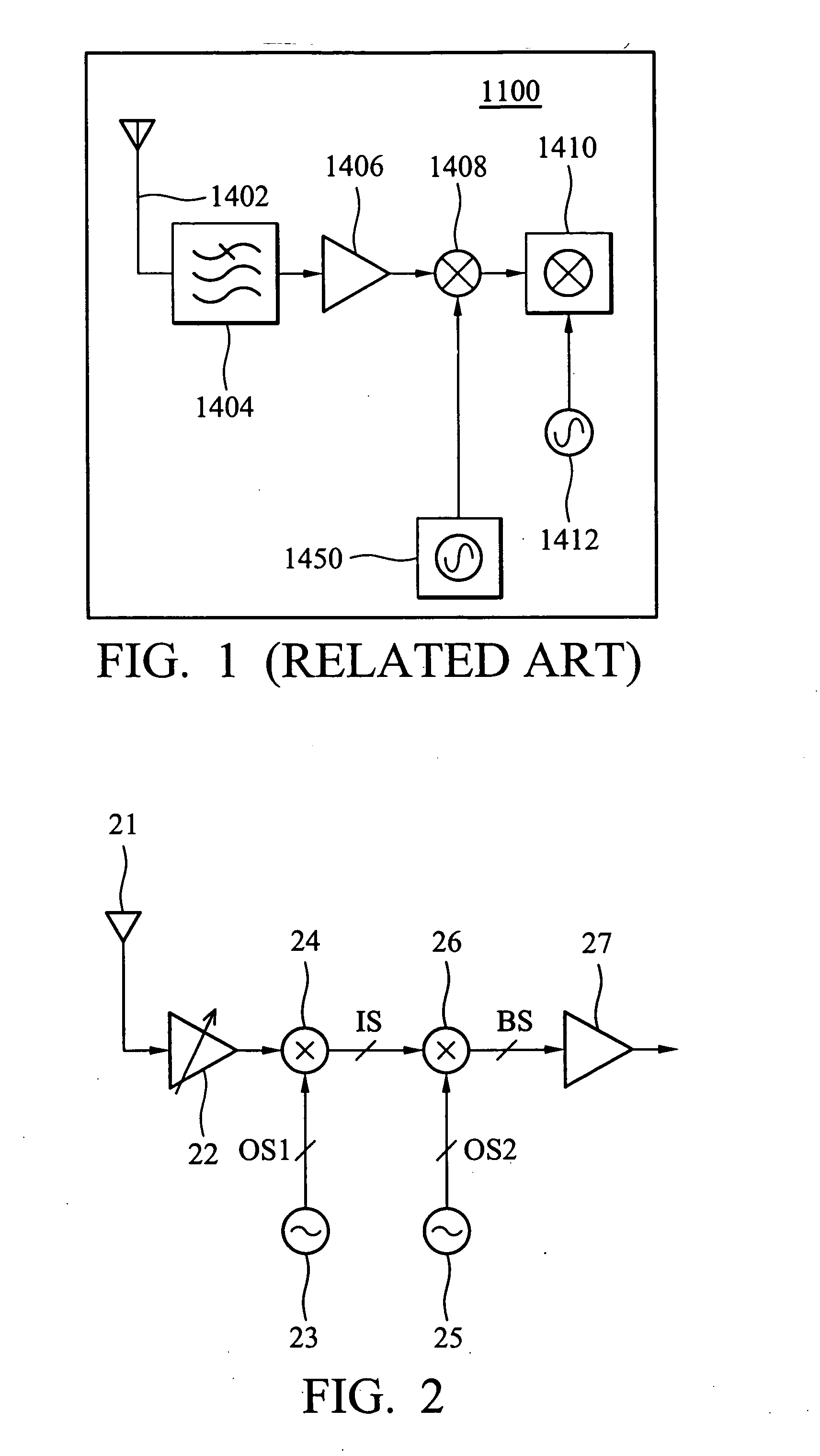
[0021]FIG. 2 is a diagram showing a TV tuner according to one embodiment of the invention. The TV tuner (receiver) includes an antenna 21 receiving an RF signal carrying information in all TV channels, a low noise amplifier 22 coupled to the antenna 21 to amplify the RF signal, a first local oscillator 23 generating a first oscillating signal OS1 having a first frequency FO1, a first mixer 24 mixing the amplified RF signal with the first oscillating signal OS1 to generate an intermediate signal IS, a second local oscillator 25 generating a second oscillating signal OS2 having a second frequency FO2, a second mixer 26 mixing the intermediate signal IS with the second oscillating signal OS2 to generate a baseband signal BS, and a SAW driver 27 coupled to an output of the second mixer 26 to drive an external SAW filter (not shown).

[0022] The first local oscillator 23 and mixer 24 form a first frequency conversion stage converting the RF signal from the radio frequency to a variable in...


PUM


Abstract

A method for frequency conversion of a receiver, including the steps of receiving a signal having a radio frequency and carrying information on a plurality of channels, selecting one of the channels, converting the signal from the radio frequency to a first variable frequency determined by the selected channel, and converting the signal from the first frequency to a desired frequency.

Description

BACKGROUND OF THE INVENTION [0001] 1. Field of the Invention [0002] The present invention relates to frequency conversion and particularly to a double or triple conversion of an RF signal in a TV tuner. [0003] 2. Description of the Prior Art [0004] Broadband tuners are used in a variety of consumer and commercial systems such as TVs, VCRs and more sophisticated devices that include cable modems and cable set-top-boxes. There are more than 300 million broadband tuners produced every year. [0005] More and more services are being offered through broadcast TV and cable operators, resulting in a rapidly evolving and convergent market. The vision of incorporating DVD, VCR, Personal Video Recording, and Internet functionality into a TV set or a set-top-box or even a personal computer is a key feature of the media center of tomorrow. [0006] Serving as the RF front-end of broadband signals, the tuner is responsible for receiving all available channels, selecting the desired channel and filte...

Claims


Application Information

Patent Timeline
Patent Type & Authority Applications(United States)
IPC IPC(8): H04N5/44H03D7/16H03L7/18H04B1/00H04B1/28
CPCH03D7/161H04B1/28H03L2207/10H03L7/18
Inventor TSENG, CHAOWENLAU, WAI
Owner QUANTEK
Why Eureka
Try Eureka