Three Phase Decanter Centrifuge

a three-phase, centrifuge technology, applied in centrifuges, rotary centrifuges, etc., can solve problems such as the freedom to perform other duties

Inactive Publication Date: 2005-09-08
HUTCHISON HAYES PROCESS MANAGEMENT
View PDF15 Cites 15 Cited by
  • Summary
  • Abstract
  • Description
  • Claims
  • Application Information

AI Technical Summary

Benefits of technology

[0009] The present invention provides a three-phase decanting centrifuge for separating solids and two phases of liquid from a slurry. Solids are removed from the slurry in the centrifuge in the conventional manner, as described above. Centrifugal action classifies the fluids, with lighter fluids (typically oil) radially closer to the axis of rotation of the machine, while the heavier fluids are radially farther from the axis, i.e. at the bottom of the bowl prior to flowing into a fluid reservoir. The lighter phase of the liquid remains within the bowl until discharged out of light phase discharge nozzles, while the heavier phase of the liquid flows into the fluid reservoir. One or more skimmer tubes dip down into the reservoir containing the heavier fluid and centrifugal action removes the heavier fluid out a

Problems solved by technology

Unfortunately, the paring disk must be adjusted by hand while monitoring the quality of the discharge.
With rapi

Method used


Image

  • Three Phase Decanter Centrifuge
  • Three Phase Decanter Centrifuge
  • Three Phase Decanter Centrifuge

Examples


Embodiment Construction

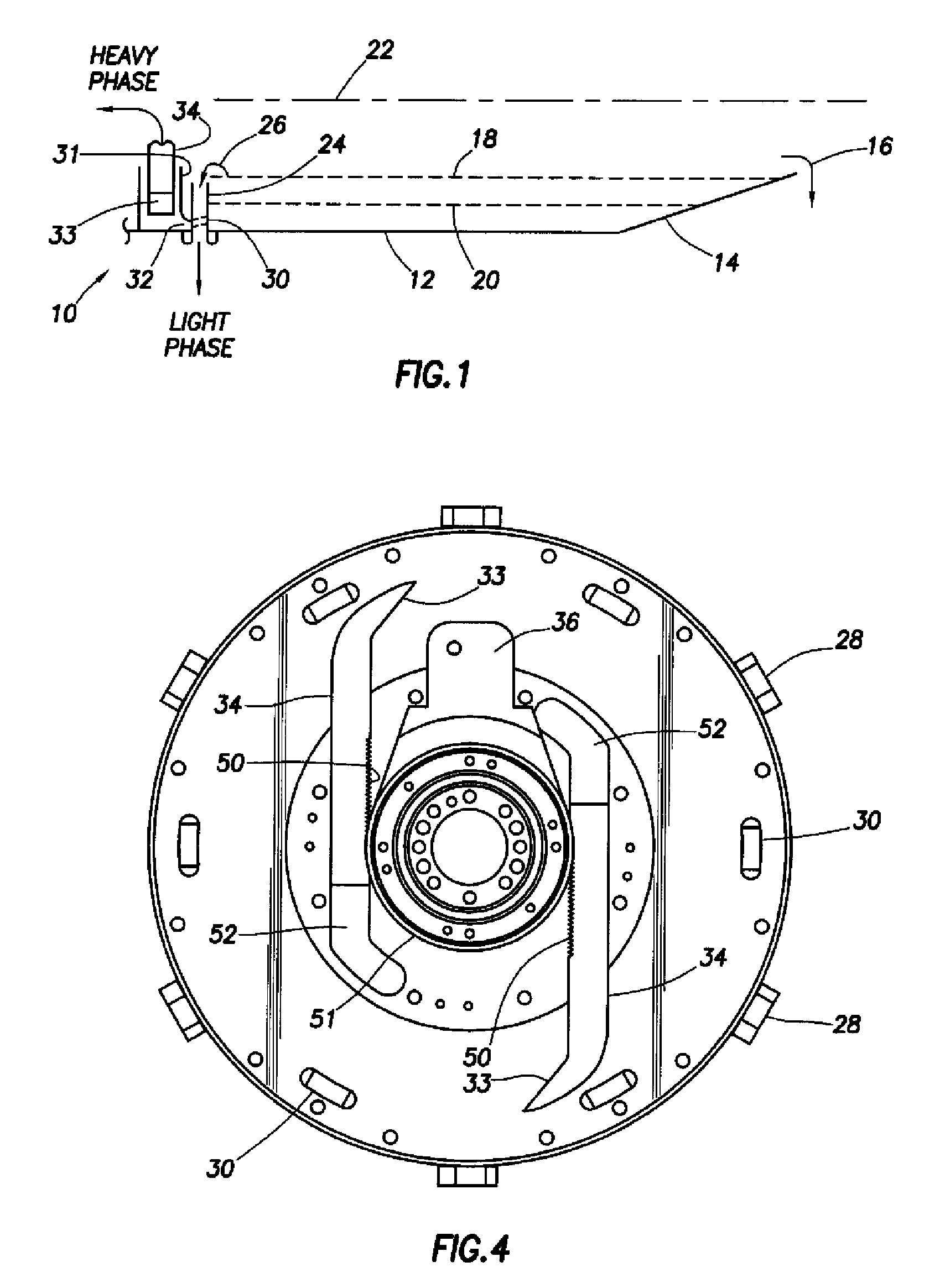
[0018] Focusing first on FIG. 1, a liquids phase separator 10 is illustrated. The separator 10 comprises a structural portion of a much larger decanting centrifuge, a portion of which is illustrated in FIG. 1. The decanting centrifuge is shown in FIG. 1 without the conventional screw conveyor or scroll in order to illustrate the three-phase separator of the present invention.

[0019] The liquids phase separator 10 includes a rapidly spinning bowl comprising a cylindrical portion 12 and a conical portion 14. Solids, separated from a slurry introduced to the centrifuge, are scrolled up the conical portion 14 of the bowl where they are discharged through a solids discharge as shown by an arrow 16. The liquid remainder of the slurry is stratified into a lighter layer 18 (typically oil or oil based component) and a heavier layer 20 (typically water). Together, the two liquids layers may be referred to as the “pond”. The entire apparatus rotates about an axis 22 in a manner well known in t...


PUM


Abstract

A three-phase decanting centrifuge is provided. Solids are removed from a slurry in the centrifuge in the conventional manner, as described above. The liquid separated from the slurry moves into a fluids reservoir. Centrifugal action classifies the fluids, with lighter fluids (typically oil) radially closer to the axis of rotation of the machine, while the heavier fluids are radially farther from the axis, i.e. at the bottom of the reservoir. Lighter fluids flow out a plurality of overflow tubes. Heavier fluids flow through a plurality of ports into a heavy fluids reservoir to be skimmed out by a pair of radially actuatable skimmer tubes. The skimmer tubes are preferably automatically operated based on the light transmissivity of the lighter and heavier fluids discharged from the machine.

Description

[0001] This application claims the benefit of U.S. Provisional Application Ser. No. 60 / 550,070 filed Mar. 4, 2004.FIELD OF THE INVENTION [0002] The present invention relates generally to the field of decanting centrifuges, and, more particularly, to centrifuge configured to separate solids from a slurry and to separate two phases of liquid which results from the solids separation. BACKGROUND OF THE INVENTION [0003] Three phase decanting centrifuges have been developed over the years to separate solids from a slurry and to separate liquid phases, such as for example oil and water. Such centrifuges are provided by such companies as FLottweg, Centrisys, and Alfa Laval. In a typical machine, as described by FLottweg, the slurry is fed through a fixed central pipe into a distributor located in the scroll of the centrifuge. The slurry to be treated is accelerated and passes through feed ports in the scroll to the bowl. [0004] Separation of solids from the slurry takes place in the conical...

Claims


Application Information

Patent Timeline
IPC IPC(8): B04B1/20B04B11/08
CPCB04B1/20B04B2001/2083B04B11/082
Inventor HENSLEY, GARY L.HILPERT, LEE
Owner HUTCHISON HAYES PROCESS MANAGEMENT
Why Eureka
Try Eureka