Guide system

Inactive Publication Date: 2005-09-15
VOLUME INTERACTIONS PTE
View PDF6 Cites 97 Cited by
  • Summary
  • Abstract
  • Description
  • Claims
  • Application Information

AI Technical Summary

Benefits of technology

[0018] The defined region is referred to as a “bounding box”, so that the user is able to display the virtual regions by moving the probe out of the bounding box. This means that the amount of movement which a user has to perform to cause the virtual buttons to be displayed is low.
[0019] To indicate one of the virtual buttons, the user may move the probe to a location within that virtual button, but more preferably he may align a length direction of the probe in the direction of the desired virtual button (e.g. towards the centre of that button with a given tolerance). This latter possibility means that the probe only needs to be mov

Problems solved by technology

Despite these strengths, the current navigation systems suffer from various shortcomings.
Firstly, the surgeon needs to look at the computer monitor and away from the surgical scene during the navigation procedure.
This tends to interrupt the surgical workflow and in practice often results in the operation being a two-people job, with the surgeon looking at the surgical scene through the microscope and his assistant looking at the monitor and prompting him.
Secondly, the interaction with the images during the surgery (e.g. switching between CT and MRI, changing the screen windows, activating markers or segmented structures from the planning phase, colour and contrast adjustments) requires the operation of a keyboard, a mouse or a touch screen, which is distracting for the surgeon and troublesome since the equipment ne

Method used


Image

  • Guide system
  • Guide system
  • Guide system

Examples


Example

[0032] Prior to performance of a surgical operation using the embodiment of the invention, the patient is scanned, such as by standard CT and / or MRI scanners. The image series thus generated is transferred to the VR environment of the Dextroscope and the data is co-registered and displayed as a multimodal stereoscopic object, in the manner disclosed in the publications describing the Dextroscope referred to above. During the planning session in the Dextroscope, the user identifies relevant surgical structures and displays them as 3D objects (a process called segmentation). Additionally, landmarks and surgical paths can be marked. Before the actual operation the 3D data is transferred to the navigation system in the OR (“operating room”, also known as “operating theatre”).

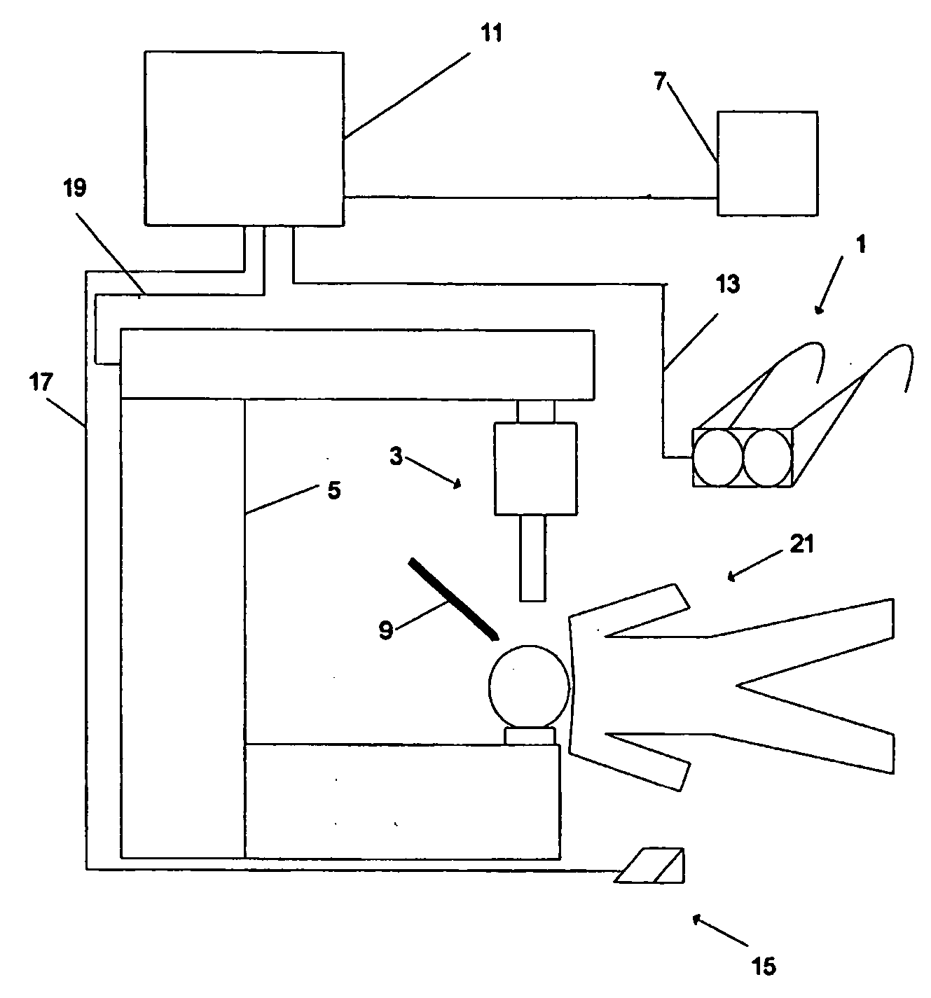
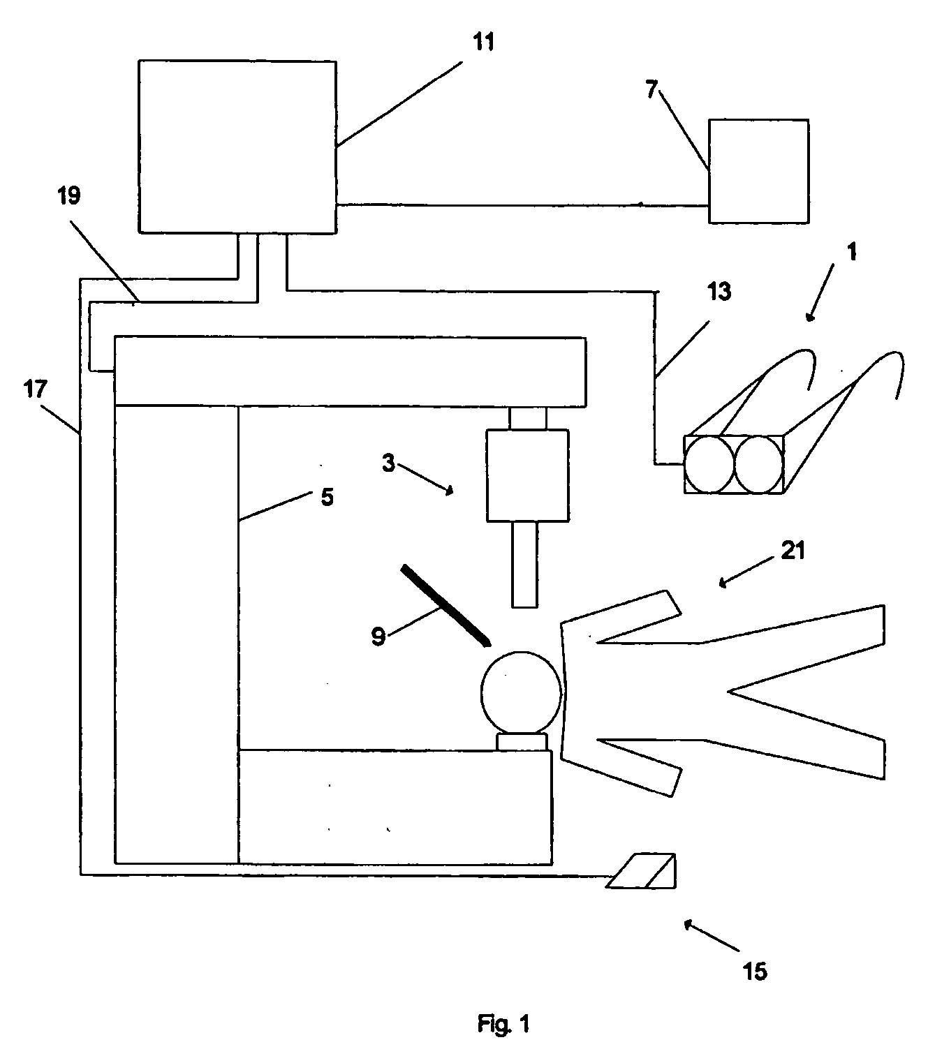
[0033] The system which is an embodiment of the present invention is shown schematically in FIG. 1, in which the various elements are not shown to scale. The system includes a stereo LCD head mounted display (HMD) ...


PUM


Abstract

A guide system for use by a user who performs an operation in a defined threedimensional region is disclosed, the system including a data processing apparatus for generating images of the subject of the operation in co-registration with the subject, a display for displaying the images to the user, a probe having a position which is visible to the user, and a tracking unit for tracking the location of the probe by the system and transmitting that location to the data processing apparatus, the data processing apparatus being arranged, upon the user moving the probe to a selection region outside and surrounding the defined region, to generate one or more virtual buttons, each of the buttons being associated with a corresponding instruction to the system, the data processing apparatus being arranged to register a selection by the user of any of the virtual buttons, the selection including positioning of the probe in relation to the apparent position of that virtual button, and to modify the computer-generated image based on the selection.

Description

FIELD OF THE INVENTION [0001] The present invention relates to a guide system, more particularly but not exclusively to a surgical navigation system for aiding a surgeon in performing an operation. The invention further relates to a method and device for controlling such a system. BACKGROUND OF THE INVENTION [0002] Image guidance systems have been widely adopted in neurosurgery and have been proven to increase the accuracy and reduce the invasiveness of a wide range of surgical procedures. Currently, image guided surgical systems (“Navigation Systems”) are based on a series of images constructed from data gathered before the operation (for example by MRI or CT) which are registered in relation to the patient in the physical world by means of an optical tracking system. To do this, detecting markers are placed on the skin of the patient and they are correlated with their counterparts visible on the imaging data. During the surgical operation the images are displayed on a screen in 3 ...

Claims


Application Information

Patent Timeline
IPC IPC(8): A61B19/00G06F3/0481G06F3/0484G06T17/40
CPCA61B19/52A61B19/5244A61B19/56A61B2019/502A61B2019/5255G02B2027/0187A61B2019/5291A61B2019/5297G02B27/017G02B2027/0134G02B2027/014A61B2019/5268A61B2034/102A61B90/36A61B2034/2055A61B2034/2068A61B2090/368A61B34/20A61B34/25A61B2090/365
Inventor AHMED, SYED NADEEMKOCKRO, RALF ALFONS
Owner VOLUME INTERACTIONS PTE
Why Eureka
Try Eureka