

Permanent magnet electromagnetic actuator for an electronic valve actuation system of an engine
a permanent magnet electromagnetic actuator and actuator technology, applied in the direction of mechanical equipment, machines/engines, non-mechanical valves, etc., can solve the problems of reducing engine peak power, difficult to accurately control the armature and/or seat landing speed, and creating noise and wear, etc., to achieve the effect of increasing the space for the permanent magnet, avoiding or reducing the increase of the coil resistan
- Summary
- Abstract
- Description
- Claims
- Application Information
AI Technical Summary
Benefits of technology
Problems solved by technology
Method used
Image

Examples
Embodiment Construction
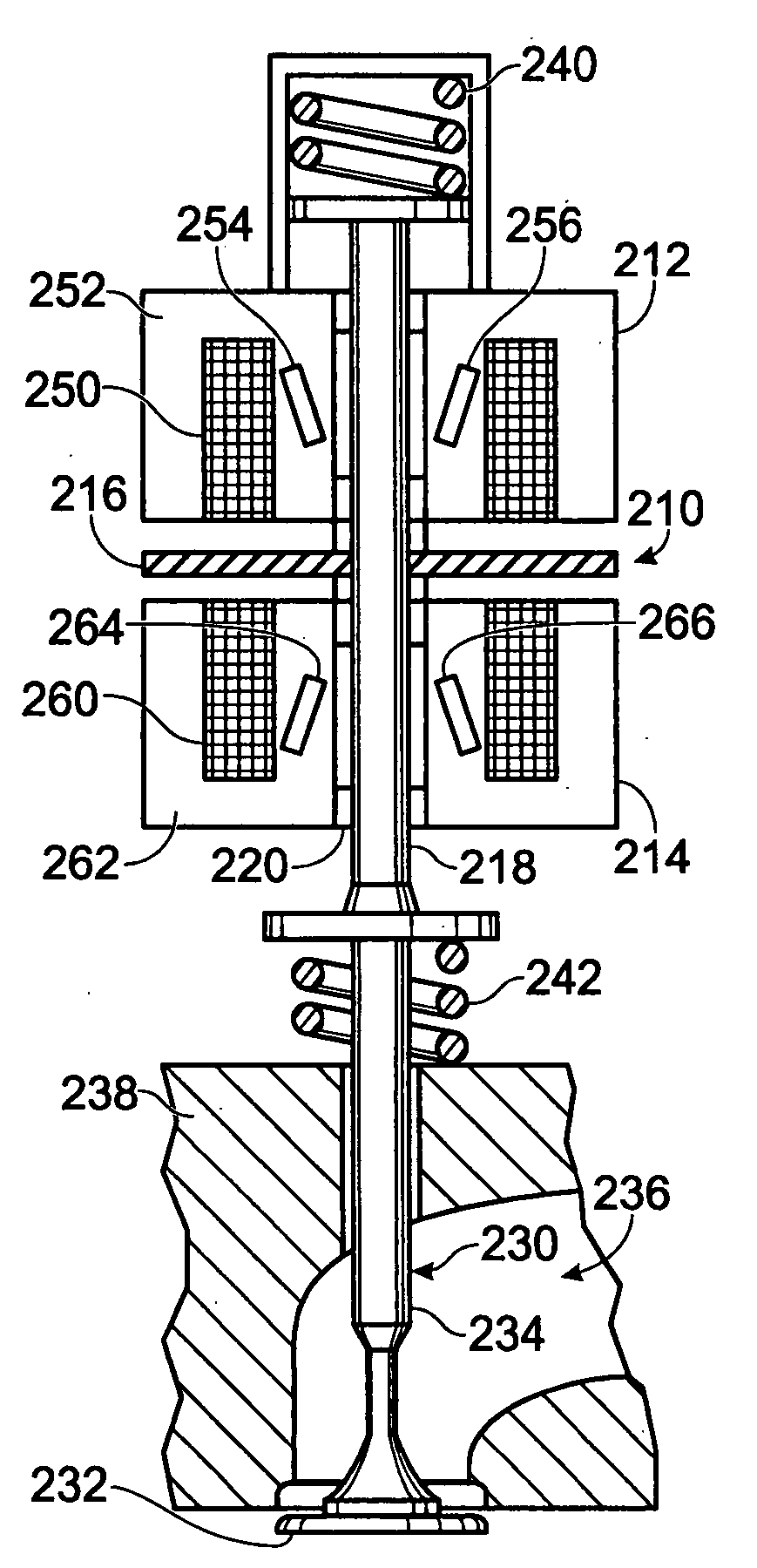
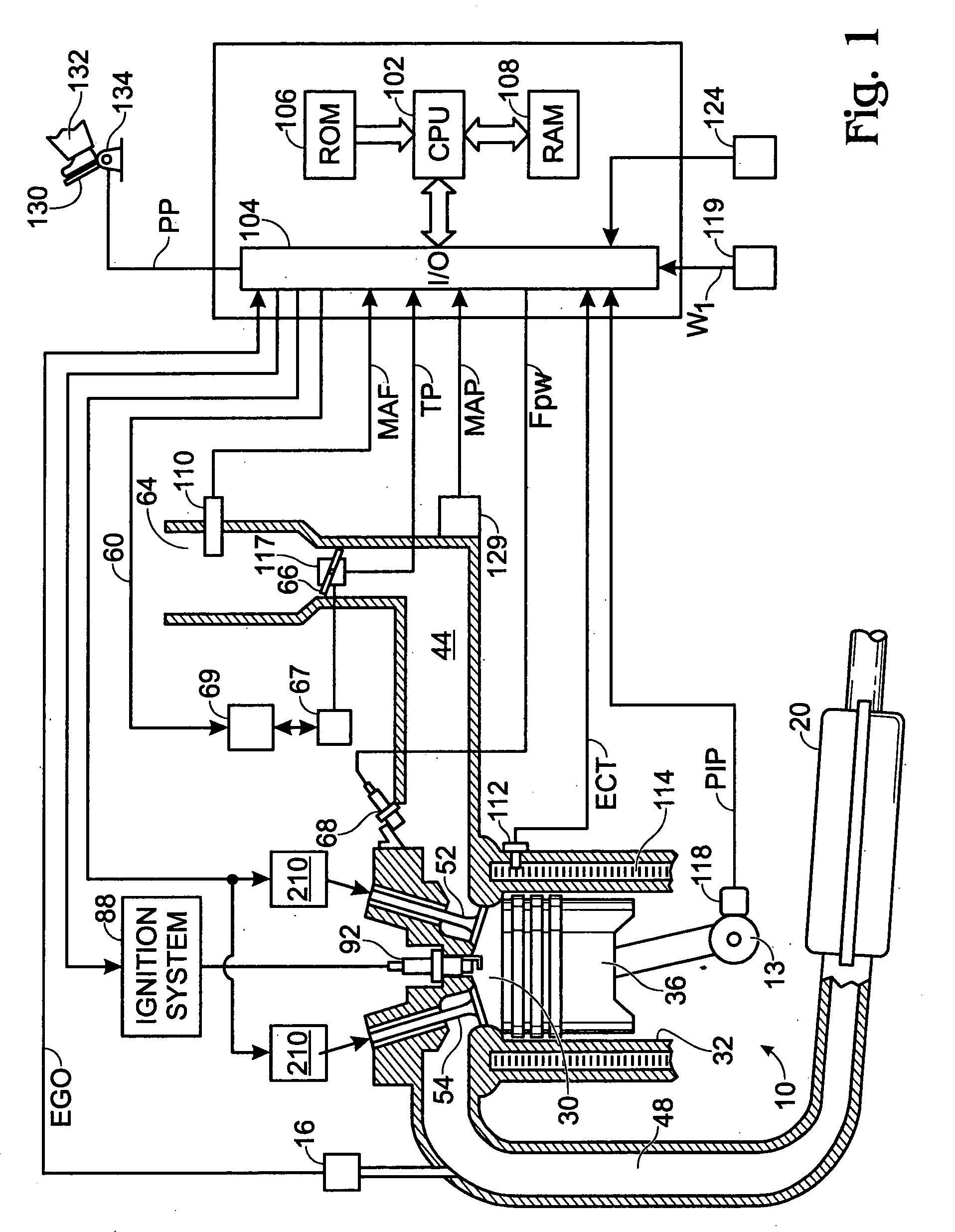
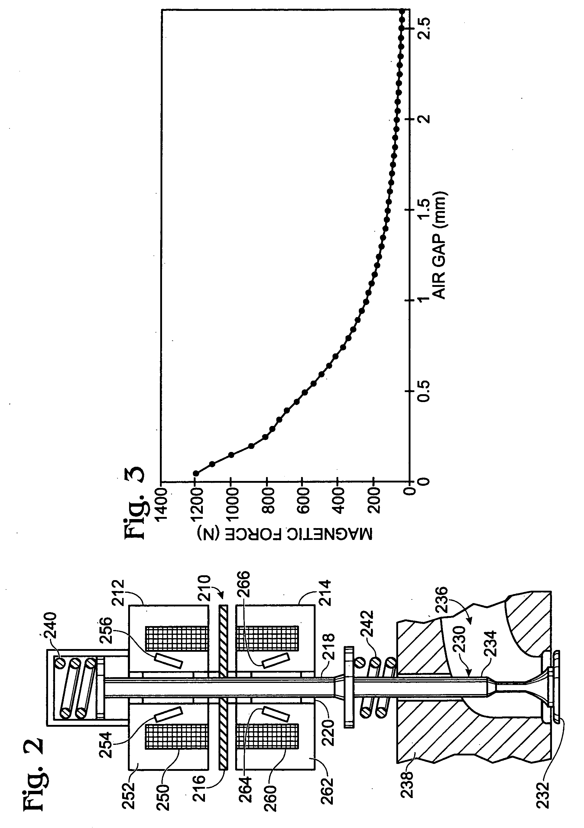
[0025] This disclosure outlines an electromagnetic actuator that can provide advantageous operation, especially when used to actuate a valve of an internal combustion engine, as shown by FIGS. 1-2. This improved actuator may result in a lower cost and lower component requirements, while maintaining desired functionality.
[0026] As a general background, several of the hurdles facing electromechanical actuators for valves of an engine are described.
[0027] A first example issue relates to engine noise and valve durability. For every two engine crank-shaft revolutions the armature of the EVA actuator of each engine valve “lands” on the upper and lower core once, the armature stem lands on the valve stem once, and the valve lands on the valve seat once (4 impacts). To meet the engine noise targets, the landing speeds of the armature and valve are controlled so as not to exceed a certain level. However, due to the fact that the rate of change of the actuator magnetic force between the ar...
PUM
 Abstract
Description
Claims
Application Information