Image forming apparatus with recording medium support member adjustable in position for desired position of uppermost recording medium on support member

a technology of image forming apparatus and recording medium, which is applied in the direction of thin material processing, instruments, and article separation, can solve the problems of increasing manufacturing cost, and achieve the effect of increasing manufacturing cos

Active Publication Date: 2005-10-06
BROTHER KOGYO KK
View PDF8 Cites 21 Cited by
  • Summary
  • Abstract
  • Description
  • Claims
  • Application Information

AI Technical Summary

Benefits of technology

[0013] However, the above configuration disclosed in the above Japanese Patent, when practiced with an additional drive sour

Problems solved by technology

However, the above configuration disclosed in the above Japanese Patent, when practiced with an additional drive source f

Method used


Image

  • Image forming apparatus with recording medium support member adjustable in position for desired position of uppermost recording medium on support member
  • Image forming apparatus with recording medium support member adjustable in position for desired position of uppermost recording medium on support member
  • Image forming apparatus with recording medium support member adjustable in position for desired position of uppermost recording medium on support member

Examples


first embodiment

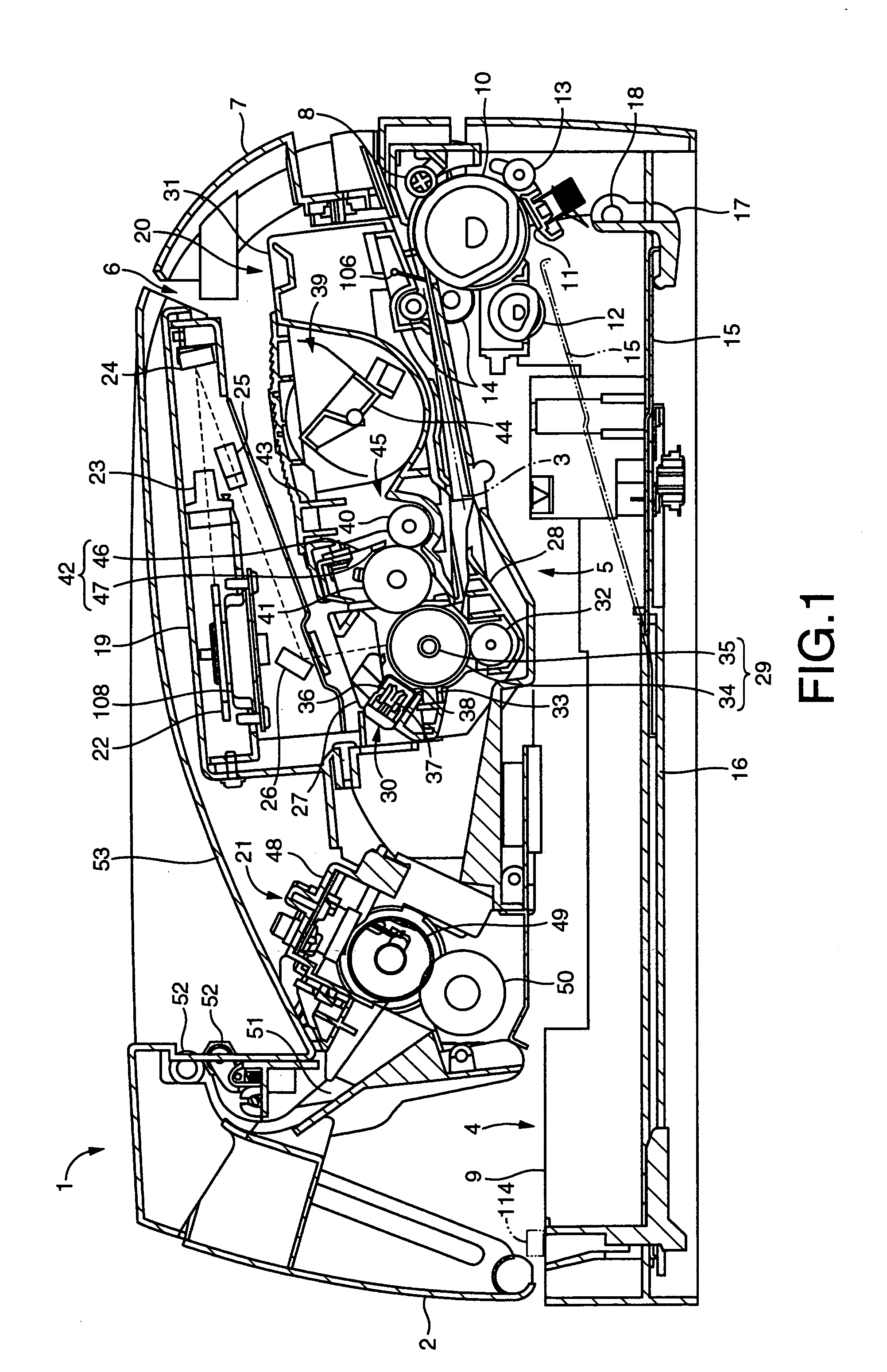
[0334] Ones of the components of the laser printer 1 according to the present embodiment common to those of the first embodiment are referenced in FIG. 11 the same reference numerals as those in FIG. 7, the details of which will be omitted in description below.

[0335] The laser printer 1 according to the present embodiment includes a drum clutch 115 in the form of an electromagnetic clutch as a shifter. The drum clutch 115, which is interposed between gears of the intermediate gear group 99 (see FIG. 6), and which is interposed between the main motor 95 and the photosensitive drum 29, as shown in FIG. 11, is electrically coupled as a controlled element with the controller 102a including the CPU 103.

[0336] The CPU 103 executes operation programs stored in the ROM 104 for controlling an on / off state (an engaged / disengaged state) of the drum clutch 115, to thereby control the connection between the motor gear 97 (see FIG. 6) and the drum gear 98 (see FIG. 6), with respect to whether th...

third embodiment

[0368] Then, the present invention will be described with reference to FIGS. 1, 7, and 14.

[0369] A laser printer 1 according to the present embodiment includes components identical in construction to those of the laser printer 1 according to the first embodiment shown in FIGS. 1 and 7. The laser printer 1 according to the present embodiment further includes a tray sensor 114 shown in phantom line in FIGS. 1 and 7.

[0370] As shown in phantom line in FIG. 1, the tray sensor 114 is disposed at the body casing 2, and functions as a sensor detecting whether or not the feed tray 9 has been attached to the body casing 2. As shown in phantom line in FIG. 7, the output from the tray sensor 114 enters the CPU 103.

[0371] The tray sensor 114 may be a contact-type sensor, for example, which is configured to detect an attached state in which the feed tray 9 has been attached to the body casing 2, in response to the tray sensor 114's mechanical contact with the rear end of the body casing 2 upon ...

fourth embodiment

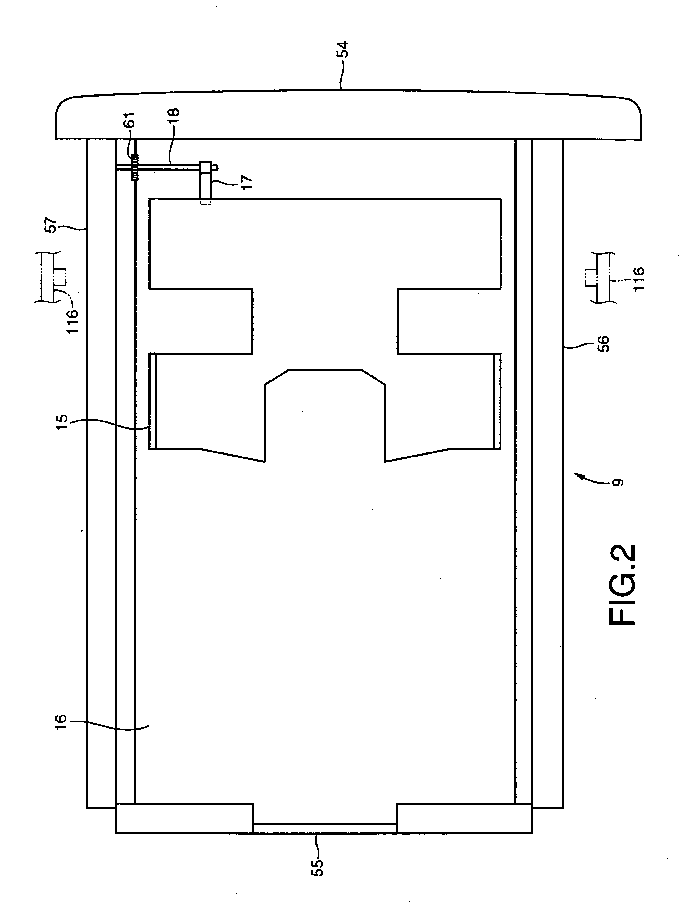
[0376] Then, the present invention will be described with reference to FIGS. 2, 7, and 15.

[0377] A laser printer 1 according to the present embodiment includes components identical in construction to those of the laser printer 1 according to the first embodiment shown in FIGS. 1, 2 and 7. The laser printer 1 according to the present embodiment further includes a pressure plate position sensor 116 shown in phantom line in FIGS. 2 and 7.

[0378] As shown in phantom line in FIG. 2, the pressure plate position sensor 116 is disposed at the body casing 2, and functions as a sensor detecting whether or not the sheet pressure plate 15 is located at the feeding position with the feed tray 9 attached to the body casing 2. As shown in phantom line in FIG. 7, the output from the pressure plate position sensor 116 enters the CPU 103.

[0379] The pressure plate position sensor 116 may be a photo-interrupt-type sensor, for example, which is configured to include a light emitter and a light receiver...


PUM


Abstract

An apparatus for forming an image on a recording medium is disclosed which includes: a first drive source; a photoreceptor driven for movement by a driving force applied thereto from the first drive source; a support member supporting the recording medium to be fed toward the photoreceptor, displaceable between a receiving position allowing reception of the recording medium on the support member, and a feeding position allowing feeding of the recording medium from the support member toward the photoreceptor; and a drive mechanism operable by a driving force applied thereto from the first drive source to displace the support member from the receiving position to the feeding position.

Description

[0001] This application is based on Japanese Patent Application No. 2004-107320 filed Mar. 31, 2004, the content of which is incorporated hereinto by reference. CROSS-REFERENCE TO RELATED APPLICATIONS [0002] Not Applicable. BACKGROUND OF THE INVENTION [0003] 1. Field of the Invention [0004] The invention relates to a technique of forming an image on a recording medium which is supported by a support member and which is to be fed to a photoreceptor, and more particularly to a technique of adjusting the position of the support member for a desired position of an uppermost recording medium on the support member. [0005] 2. Description of the Related Art [0006] In general, image forming apparatuses such as printers are each configured to include a feeder tray for feeding a recoding medium in the form of a recording sheet of paper, for example. The feeder tray includes a sheet pressure plate on which a stack of recording sheets are received, or onto which a stack of recording sheets are l...

Claims


Application Information

Patent Timeline
IPC IPC(8): B65H1/08B65H1/14G03G21/14B65H3/06B65H3/52G03G15/00
CPCB65H2403/722B65H3/0669
Inventor DAN, KENICHI
Owner BROTHER KOGYO KK
Why Eureka
Try Eureka