Concrete-mortar transfer system of concrete pump car

a transfer system and concrete technology, applied in the direction of pump parameters, fluid couplings, servomotors, etc., can solve the problems of reducing the efficiency of concrete pump cars, and reducing the cost of various building constructions. , to achieve the effect of maximizing customer satisfaction, reducing the cost of various building constructions, and simple operation

Inactive Publication Date: 2005-10-20
DNS
View PDF6 Cites 32 Cited by
  • Summary
  • Abstract
  • Description
  • Claims
  • Application Information

AI Technical Summary

Benefits of technology

[0017] Accordingly, it is an object to provide a concrete transfer system of a concrete pump car in which when increasing or decreasing the transfer distance, it is not required to perform a separation or a change work and the concrete can be selectively transferred with a high or a low pressure by a simple operation, thereby reducing the cost of the various building constructions, the construction period and simultaneously maximizing the customer's satisfaction.
[0019] Preferably, a check valve is installed on the oil pressure line between the high / low pressure selection valve and a reverse current preventive device for preventing a reverse current from generating toward the reverse current preventive device.

Problems solved by technology

However, in the conventional concrete transfer system as shown in FIG. 2, oil with a constant pressure is always supplied to a rod side a of the drive cylinder from the oil pressure pump 60, so that the force for advancing the piston by the fluid inputted to the inside of the cylinder is comparatively weaker (than the structure that the fluid is inputted to the piston side of the drive cylinder), so that it is only possible to transfer the concrete with a short distance.
Accordingly, because the unit area of the piston at the rode side is smaller than the inside area of the cylinder piston, in the conventional concrete transfer system, because the fluid(oil pressure oil) is only always supplied to the rod side, the force applied to the rod is weak, accordingly, the force of the pressure pistons 44 and 54 for performing a sucking and discharging operation within the concrete input tube become weak, so that there is a disadvantage that it can be only used for transferring a short distance.
However, at this time, there are several problems that since each oil horse must be separated and assembled by exchanging with the combining positions, so that the working is very difficult and it is required much time in the exchanging work.
Also, since various devices are mounted to the concrete transfer system, it is difficult to separate and assemble the devices in the narrow places.
In addition, since the length of the drive cylinder is very long and all oil pressure horses also must be formed very long for changing the connection positions of the oil pressure horses, the concrete transfer system become very complex and it is difficult to mount the system to the pump car.
Especially, when the oil pressure horses are separated for changing the connection positions, the pressure oil is discharged, so that when the oil must not be injected again after assembling, the device dose not work in proper.
Also, there may be occurred a contamination of the pump car or a serious environment contamination due to the oil leaked at the circumference.

Method used


Image

  • Concrete-mortar transfer system of concrete pump car
  • Concrete-mortar transfer system of concrete pump car
  • Concrete-mortar transfer system of concrete pump car

Examples


Embodiment Construction

[0030] A concrete transfer system of a concrete pump car in accordance with preferred embodiments of the present invention will now be described in detail with reference to the accompanying drawings.

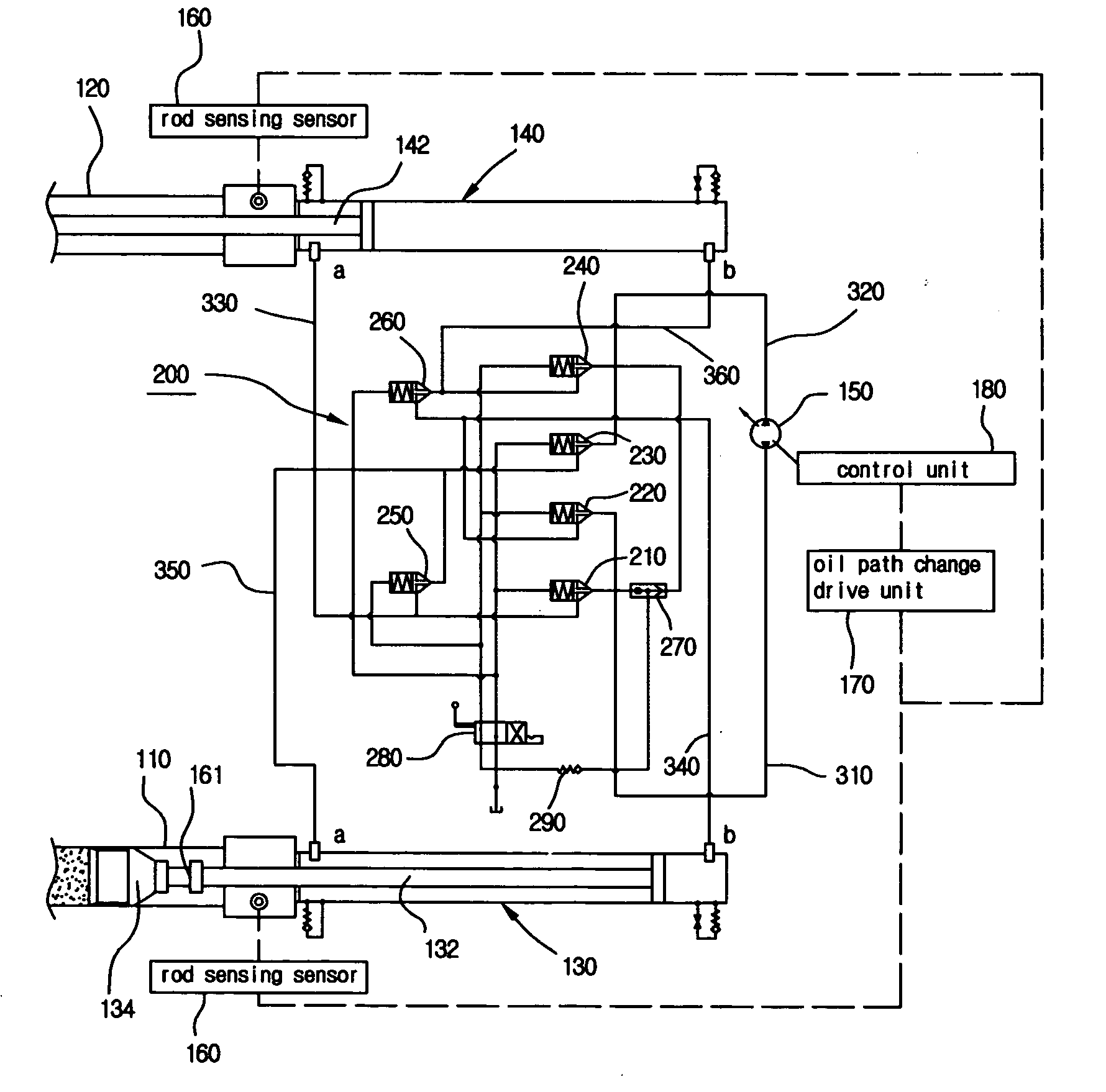
[0031]FIG. 3a is an outline oil pressure circuit diagram illustrating a concrete transfer system of a concrete pump car in accordance with an embodiment of the present invention, FIG. 3b is a partially enlarged view of FIG. 3a, and FIG. 4 is an oil pressure circuit diagram illustrating a concrete transfer system of a concrete pump car in accordance with an embodiment of the present invention.

[0032] As shown in FIGS. 3 and 4, a concrete transfer system of a concrete pump car comprises a pair of concrete input tubes 110 and 120 mounted in union to a pair of communication holes punched to the inside surface of a hopper, first and second drive cylinders 130 and 140 mounted on the same lines of the concrete input tubes 110 and 120 for sucking and transferring the concrete by forward and bac...


PUM

PropertyMeasurementUnit
pressureaaaaaaaaaa
volumeaaaaaaaaaa
timeaaaaaaaaaa

Abstract

The present invention relates to a concrete transfer system of a concrete pump car which comprises a pair of concrete input tubes mounted in union to a pair of communication holes punched to the inside surface of a hopper, first and second drive cylinders mounted on the same lines of the concrete input tubes for sucking and transferring the concrete by forward and backward movements of pressure pistons mounted to rod ends, an oil pressure pump for supplying the fluid to the first and second drive cylinders, a rod sensing sensor for sensing the movement of the rods of the first and second drive cylinders, a control unit for performing a predetermined control operation by receiving the sensing signal of the rod sensing sensor, an oil path change drive unit for supplying selectively the fluid with the first and second drive cylinders according to the control signal of the control unit, the concrete transfer system of the concrete pump car comprising: a first logic valve to sixth logic valves, a reverse current preventive device, and a high / low pressure selection valve.

Description

BACKGROUND OF THE INVENTION [0001] 1. Field of the Invention [0002] The present invention relates to a concrete-mortar transfer system of a concrete pump car in which the concrete transfer system is mounted to the concrete pump car for transferring the mortar concrete to a placing position at a construction job-site and when increasing / decreasing the transfer distance of the concrete, a work for separating or changing the concrete pump car is not required, thereby selectively capable of transferring the concrete with a high or a low pressure by a simple operation. [0003] 2. Description of the Background Art [0004] Generally, a pump car is an equipment for transferring the fluent mortar concrete to the placing position of the concrete and includes a transfer system for transferring the mortar concrete(hereinafter, referred as concrete) with pressure. The transfer system sucks the concrete inputted to a hopper from a ready-mixed concrete car and thereafter transfers it to the placing ...

Claims


Application Information

Patent Timeline
Patent Type & Authority Applications(United States)
IPC IPC(8): B28C7/04E04G21/04F04B9/105F04B9/117F04B15/02
CPCF04B9/105F04B2201/0201F04B15/023F04B9/1172B65F1/1415B65B67/1233A47B13/00B65F2240/112B65F2240/12
Inventor JUNG, CHUL JONG
Owner DNS
Why Eureka
Try Eureka