Coordinate input device, control method therefor, and control program for implementing the method

a control method and input device technology, applied in the direction of input/output for user-computer interaction, instruments, computing, etc., can solve the problem of not having the function of proximity input provided by the coordinate input device, the distance between this thin layer and the coordinate input surface is not necessarily accurate over the entire area

Inactive Publication Date: 2006-01-12
CANON KK
View PDF13 Cites 72 Cited by
  • Summary
  • Abstract
  • Description
  • Claims
  • Application Information

AI Technical Summary

Benefits of technology

[0029] It is an object of the present invention to provide a coordinate input device which is capable of performing accurate and appropriate detection of a pen-up / pen-down state over the entire coordinate input surface, based on motion of an indication tool or the like in a direction substantially perpendicular to the coordinate input surface, and realizing a function equivalent to that of an indication tool equipped with a communication function without using the tool, and a control method therefor as well as a control program for implementing the method.

Problems solved by technology

However, the coordinate input devices proposed, in U.S. Pat. No. 4,507,557 and Japanese Laid-Open Patent Publications (Kokai) No. 2000-105671 and No. 2001-142642 are not equipped with either the pen-up / pen-down determining function or the proximity input function, and therefore they have a problem in terms of accuracy in coordinate input operation.
Of course, such coordinate input devices are not provided with the proximity input function.
However, the coordinate input devices disclosed in Japanese Laid-Open Patent Publications (Kokai) No. 2002-091701 and No. 2001-084106 suffer from the following problems.
However, the distance between this thin layer and the coordinate input surface is not necessarily accurately constant over the entire area.
Therefore, it is difficult to determine the pen-up / pen-down state accurately by the above described method.
Further, since the retroreflective zone is thin, a range enabling detection of light shading is narrow, which makes it difficult to fully exert the proximity input function.
For this reason, an adequate proximity input function cannot be provided.
However, the coordinate input device proposed in Japanese Laid-Open Patent Publication (Kokai) No. 2001-084106 is not capable of determining the pen-down state in the vicinity of the position P3 or P4 of the pen 105, which is a negative aspect of the coordinate input device in terms of the operability of the pen 105.
However, the light-shading-type touch panel provided with the indication tool having the above-mentioned communication function has the following disadvantages: First, it is necessary to transmit the pen-down signal, and hence the pen per se is complicated (expensive, larger in size).
Secondly, since it is necessary to transmit the pen-down signal, a power supply (battery or the like) is needed for the signal transmission.
Thirdly, since it is necessary to transmit the pen-down signal, the thickness of the retroreflective zone 100 is limited to prevent an excessive increase in depth of a frame portion surrounding the coordinate input surface, and therefore the range within which light shading can be detected is narrowed, which makes it difficult to fully exert the proximity input function.

Method used


Image

  • Coordinate input device, control method therefor, and control program for implementing the method
  • Coordinate input device, control method therefor, and control program for implementing the method
  • Coordinate input device, control method therefor, and control program for implementing the method

Examples


Embodiment Construction

[0073] The present invention will now be described in detail with reference to the accompanying drawings showing a preferred embodiment thereof.

[0074] First, a description will be given of the outline of an embodiment of the present invention.

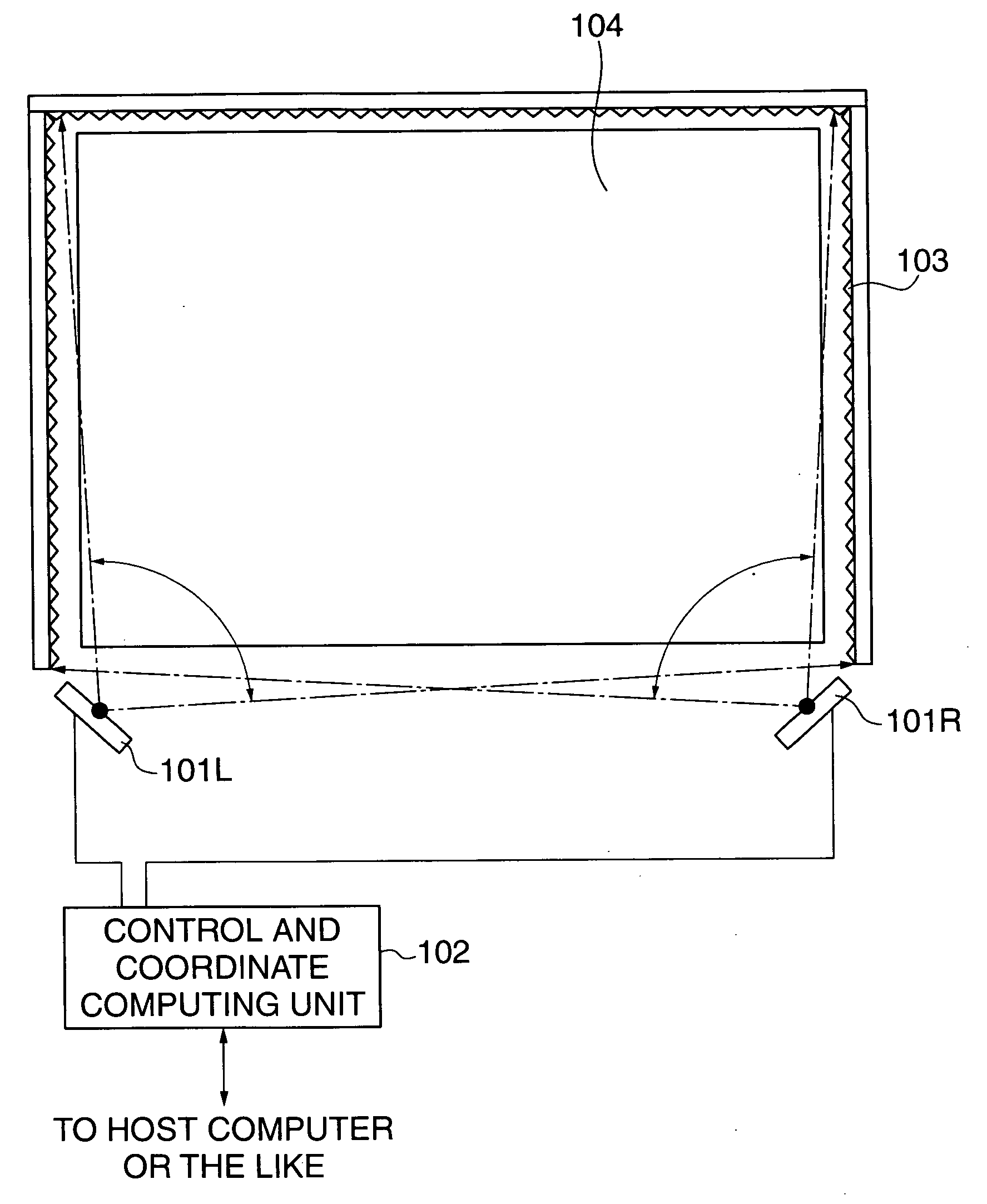
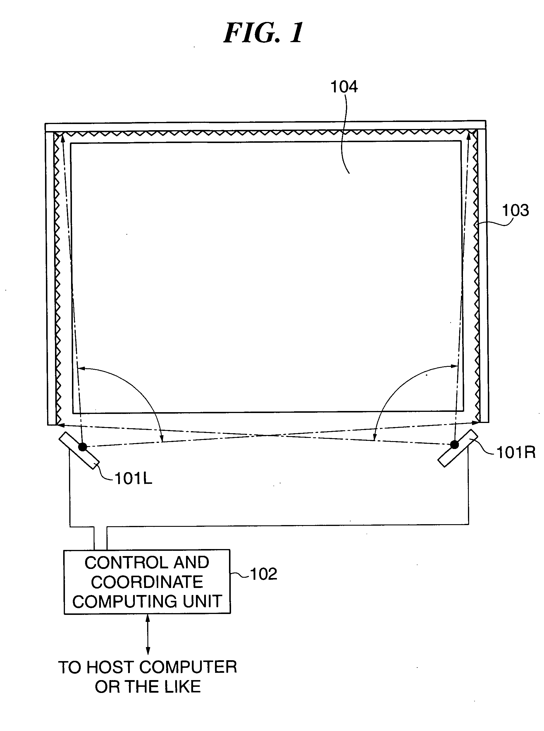
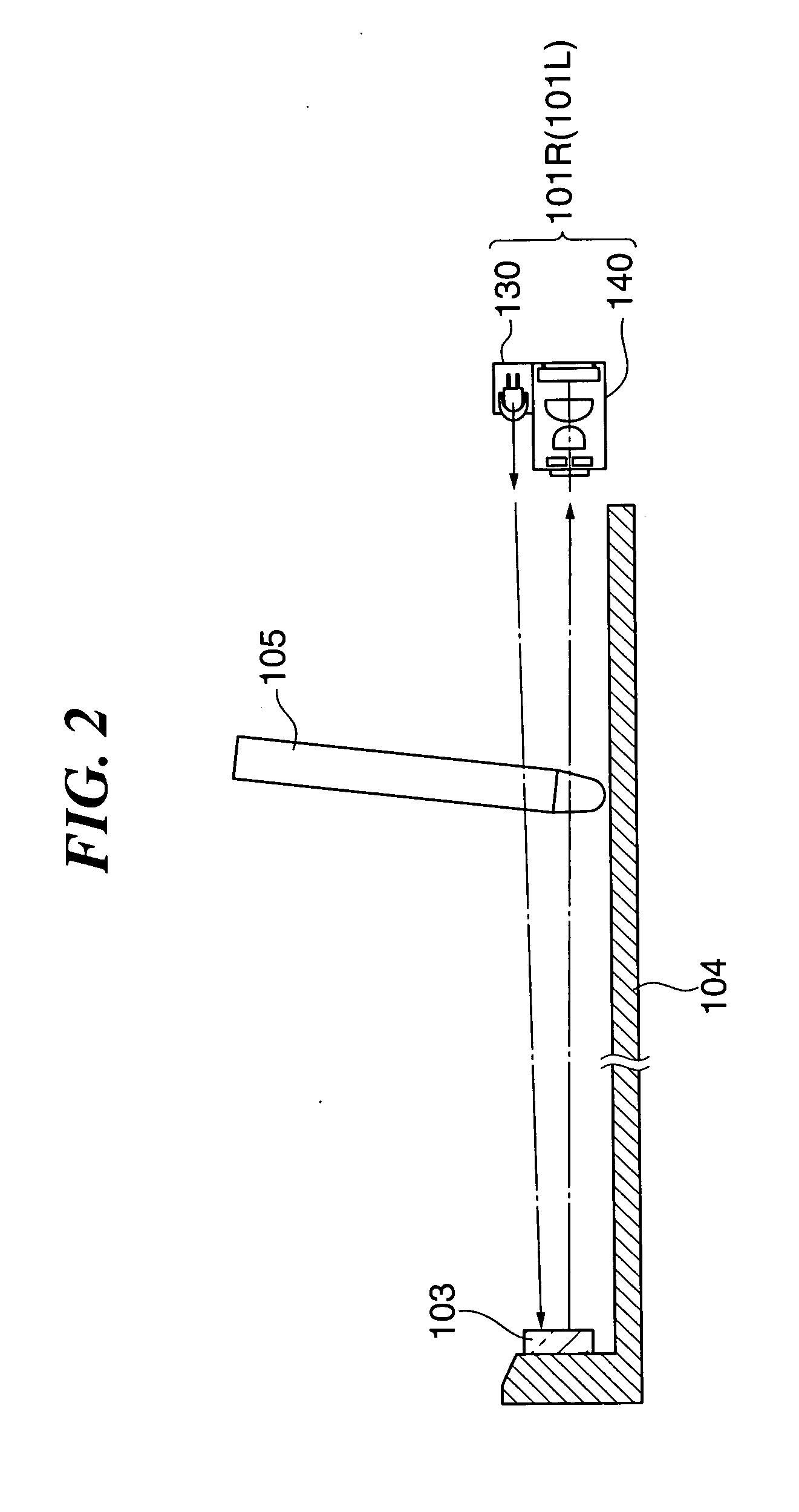
[0075]FIG. 1 is a plan view showing the overall hardware configuration of a coordinate input device according to the present embodiment, and FIG. 2 is a view schematically showing the construction of the coordinate input device in FIG. 1, as viewed from a lateral side thereof.

[0076] The coordinate input device is provided with a coordinate input surface (input area) 104 having a rectangular shape, for example, and a retroreflective member 103 is disposed in a manner surrounding three sides of the coordinate input surface 104 in a frame shape. The coordinate input surface 104 is implemented by a display screen of a display device, such as a PDP, a rear projector, or a LCD panel, such that it can be used as an interactive input device.

[0077] ...


PUM


Abstract

A coordinate input device which is capable of performing accurate and appropriate detection of a pen-up / pen-down state over the entire coordinate input surface, based on motion of an indication tool or the like in a direction substantially perpendicular to the coordinate input surface, and realizing a function equivalent to that of an indication tool equipped with a communication function without using the tool. A light-shaded position shaded from light on the coordinate input surface by input of the indication tool on the coordinate input surface is detected, and then the coordinates of the light-shaded position are calculated. Further, the pen-up / pen-down state of the indication tool is determined based on a temporal change in light shading in the light-shaded position.

Description

BACKGROUND OF THE INVENTION [0001] 1. Field of the Invention [0002] The present invention relates to a coordinate input device capable of detecting a position indicated by a pen or the like on an input surface and determining the coordinates of the position, and a control method therefor as well as a control program for implementing the method. [0003] 2. Description of the Related Art [0004] In general, a coordinate input device is used to control a computer connected to the coordinate input device or write letters or figures by indicating a position on a coordinate input surface by a light-shading member, such as an indication tool or a finger, to thereby input the coordinates of the position. [0005] Conventional coordinate input methods employed by the coordinate input devices of the above-mentioned type include ones using a resistance film, ones using ultrasound, ones using light, and other various methods. A method using light has been disclosed e.g. in U.S. Pat. No. 4,507,557. ...

Claims


Application Information

Patent Timeline
Patent Type & Authority Applications(United States)
IPC IPC(8): G09G5/00G06F3/03G06F3/041G06F3/033G06F3/042
CPCG02B5/124G06F3/0428G06F3/0423G06F3/03542
Inventor KOBAYASHI, KIWAMU
Owner CANON KK
Why Eureka
Try Eureka