Adaptive coupling equalization in beamforming-based communication systems

a beamforming and coupling equalization technology, applied in the field of audio systems, can solve the problems of prohibitive computational cost, complex adaptation beamforming system, and computational intensiveness, and achieve the effect of reducing the cost of adaptation

Active Publication Date: 2007-04-26
MITEL
View PDF9 Cites 65 Cited by
  • Summary
  • Abstract
  • Description
  • Claims
  • Application Information

AI Technical Summary

Benefits of technology

[0010] It is an object of the present invention to obviate or mitigate at least one disadvantage of previous beamforming-based communication systems, particularly sector-based beamforming systems.
[0014] In a further aspect there is provided a method for achieving rapid convergence of an acoustic echo canceller in a switched beamforming-based communication system. The method includes the steps of adaptively equalizing coupling responses of inactive beamformers in a beamformer array to a coupling response of a currently active beamformer in the array; applying acoustic echo cancellation to an output of the currently active beamformer; switching one of the inactive beamformers to be the currently active beamformer in response to a change in input characteristics; and repeating the above steps. In embodiments of this aspect of the present invention, the steps of adaptively equalizing and applying echo cancellation are performed concurrently. Typically, the adaptive equalization is performed during periods of far-end speech. For each inactive beamformer, adaptively equalizing the coupling responses may include generating an error signal representing the difference between coupling signals from the currently active beamformer and from the inactive beamformer; and applying adaptive beamforming, in response to the error signal, to substantially equalize the response of the inactive beamformer to the response of the active beamformer.

Problems solved by technology

Adaptive beamforming systems are complex, computationally intensive and suffer from general robustness issues, such as desired signal cancellation.
Unless it is compensated for, this phenomenon is distracting to participants in telephone calls and is considered a nuisance.
The efficient integration of beamforming and AEC continues to be a challenge.
This approach has a prohibitive computational cost, because it requires as many acoustic echo cancellers, running in parallel, as there are sensors in the device.
This approach presents a challenge to the AEC operation, because the directional signal has characteristics that vary according to the spatial area to which the system is looking.
This can result in poor echo cancellation until the AEC algorithm converges, and, accordingly, poor transitions between beamformers, particularly if the AEC does not quickly converge to the required cancellation coefficients.
These methods tend to be complex and are not optimal for sector-based beamformers, where a known number of fixed beamformers are used to cover a desired spatial area in concert with an apparatus used to switch from one beamformer to another.
The described methods are also designed for slowly varying beamformers, such as adaptive noise or interference cancellation beamformers, and do not efficiently handle sudden and possibly drastic changes that occur in a switched-beamforming structure.
It does suffer from problems, however, in non-stationary (time-varying) acoustic environments.
To be precise, if the acoustic environment, or echo path for a particular beamformer, changes significantly between two utterances of a beamformer being chosen by the localization algorithm, then the information stored in the workspace for the particular beamformer no longer provides good echo cancellation and the performance of the system will degrade.
Another drawback of this approach is that, in order to be entirely trained in terms of echo cancellation, the device needs to operate in all possible beamformer positions and perform AEC in each position.
This coupling equalization approach, however, can only provide limited improvement in practice, because the loudspeaker-coupling signal can only be known a priori with a limited accuracy.
Even if only the direct-path signal is targeted, which is reasonable since it accounts for most of the energy of the echo, other factors come into play that limit the accuracy of a priori knowledge.
Therefore, in practice, this design method can only be used to minimize the amount of information that needs to be stored in each workspace, and does not solve the problem of optimizing the integration of beamforming and AEC.

Method used


Image

  • Adaptive coupling equalization in beamforming-based communication systems
  • Adaptive coupling equalization in beamforming-based communication systems
  • Adaptive coupling equalization in beamforming-based communication systems

Examples


Embodiment Construction

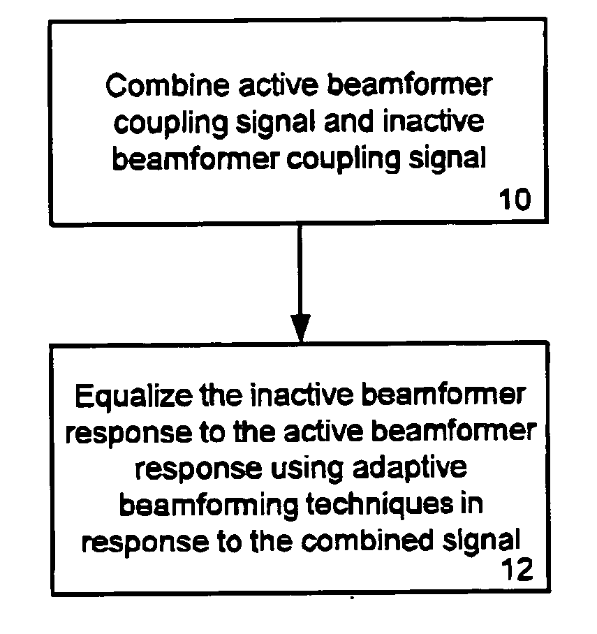
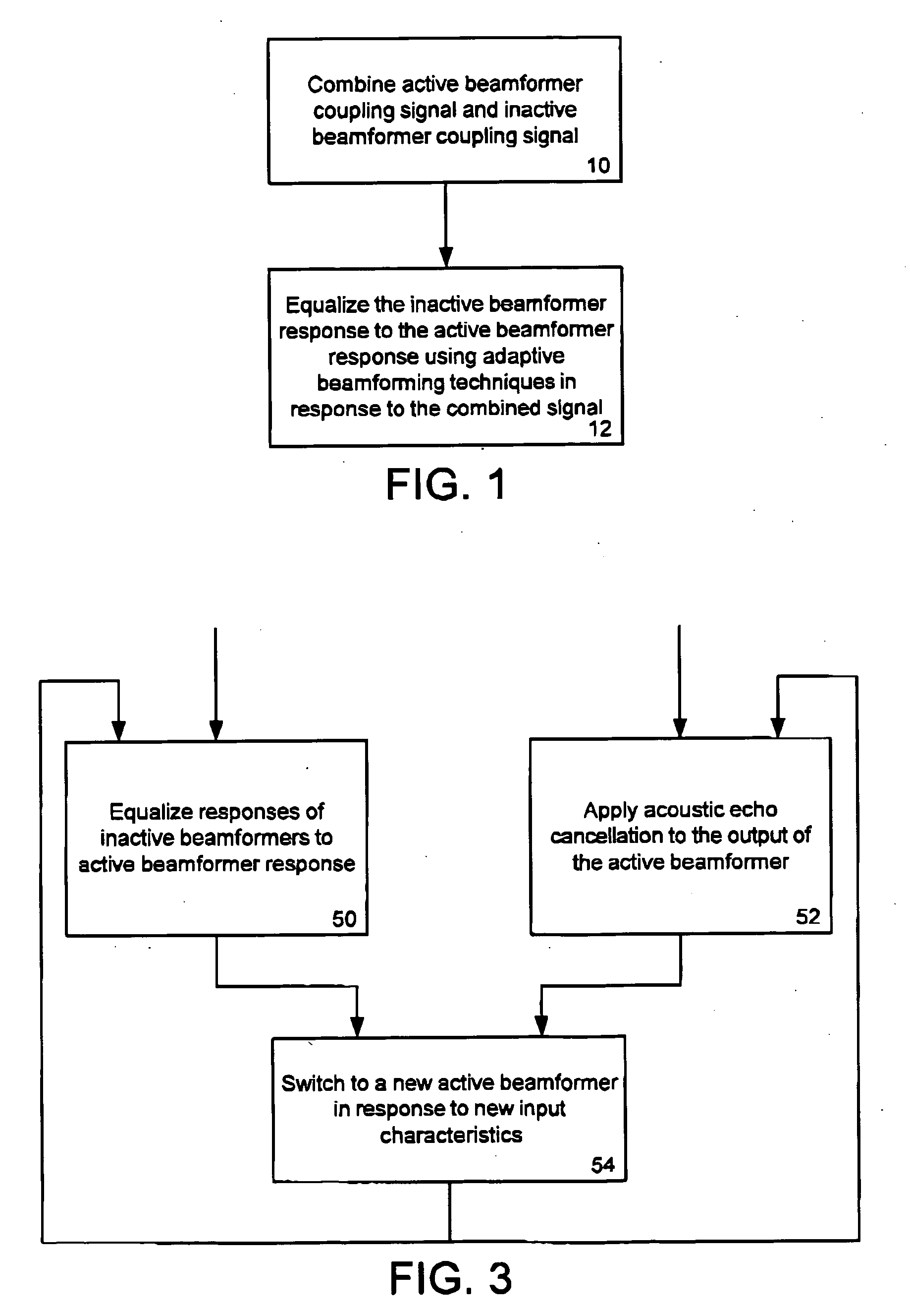
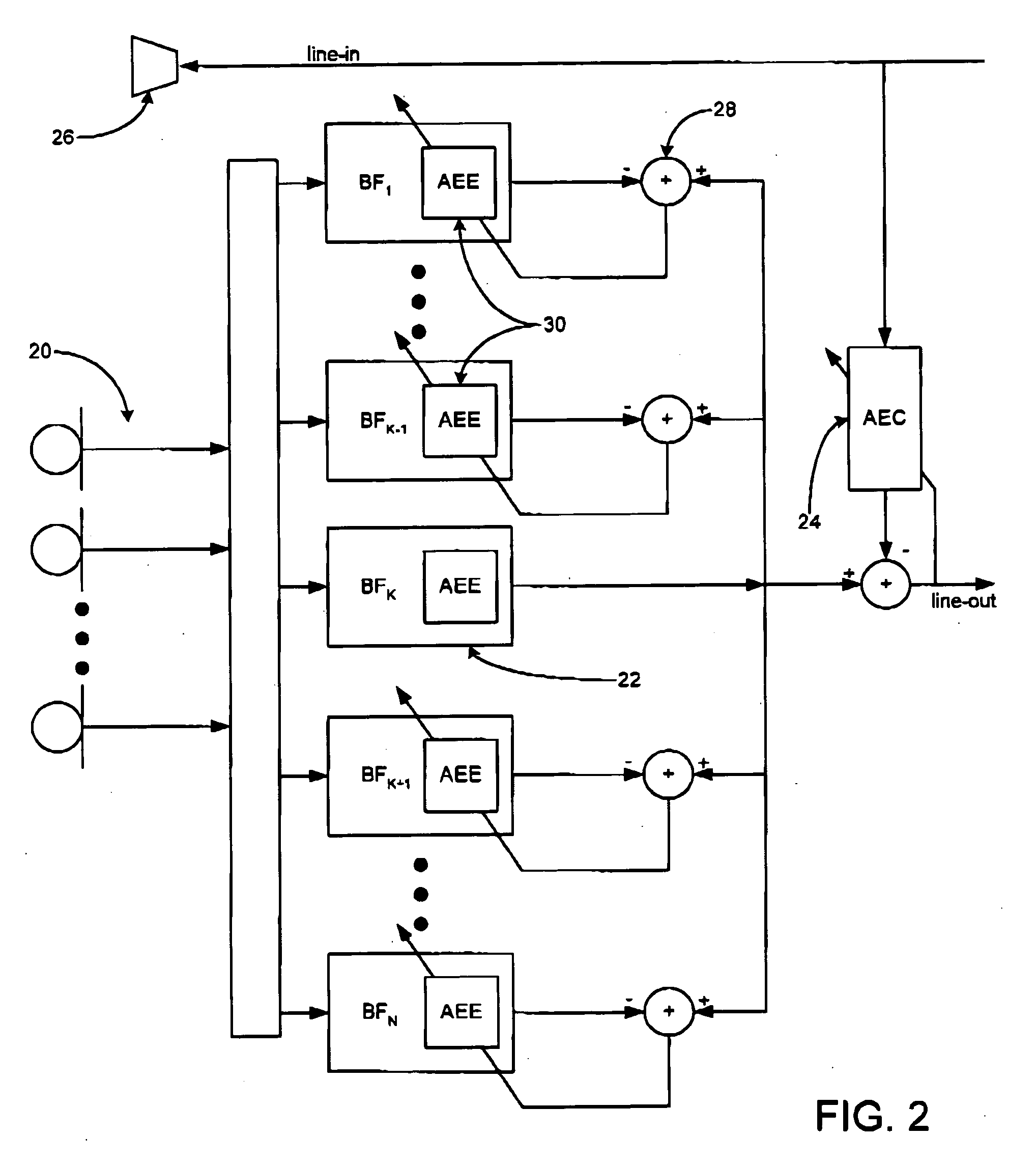
[0020] Generally, the present invention provides a method and system for rapid adaptive coupling equalization in beamforming-based communication systems, particularly sector-based beamforming systems, to provide smooth transitions for AEC when the look direction of the communication system changes and when the acoustic environment varies with time. The output of beamformers is modified in real-time, based on the real-time loudspeaker-coupling signal, in order to force the outputs to have the same response to the loudspeaker coupling signal. In other words, the beamformer outputs are equalized with respect to the loudspeaker coupling signal. This can be done with conventional adaptive beamforming techniques, including block-based, sample-based, time-domain, sub-band and frequency-domain adaptive filtering algorithms. These techniques are well known in the art of adaptive array processing, and are described in detail in e.g. D. G. Manolakis, V. K. Ingle, S. M. Kogon, Statistical And A...


PUM


Abstract

A method and system for rapid adaptive coupling equalization in beamforming-based communication systems, particularly sector-based beamforming systems, provides smooth transitions for AEC when the look direction of the communication system changes and when the acoustic environment varies with time. The coefficients of inactive beamformers are modified in real-time, using adaptive beamforming techniques based on the real-time loudspeaker-coupling signal, in order to force the outputs of inactive beamformers to have the same response to the loudspeaker coupling signal as the active beamformer does.

Description

FIELD OF THE INVENTION [0001] The present invention relates generally to audio systems. More particularly, the present invention relates to adaptive coupling equalization in beamforming-based communication systems, such as conference telephony systems. BACKGROUND OF THE INVENTION [0002] Beamforming is a technique for providing spatial directivity in communication systems, such as audio conferencing systems. Beamforming can be implemented with directional microphones, or combinations of omni-directional microphones forming a microphone array. Beamforming can be used to discriminate a source position in a noisy environment by adding a weighted combination of the signals from each microphone. This creates a desired “look” direction aimed at the source, or talker, position. Beamformers are logical elements that correspond to the combination of one or more microphone inputs. Multiple beamformers are typically provided to give a number of look directions or sectors. The beamformers can be...

Claims


Application Information

Patent Timeline
Patent Type & Authority Applications(United States)
IPC IPC(8): A61B8/00
CPCH04M3/56H04M9/085H04R1/406H04R3/005H04R2201/403H04R2430/20
Inventor BEAUCOUP, FRANCK
Owner MITEL
Why Eureka
Try Eureka