Intelligent traffic control system and method based on wireless Mesh ad hoc network

A technology of intelligent traffic control and traffic control, which is applied in the field of traffic control and intelligent traffic control, and can solve the problems of low robustness and fault tolerance, low intelligence, low reliability and flexibility, etc.

Inactive Publication Date: 2011-05-18
GUANGXI UNIVERSITY OF TECHNOLOGY
6 Cites 84 Cited by

AI-Extracted Technical Summary

Problems solved by technology

The patent publication number is: CN101079772A "intelligent traffic control system based on ZigBee wireless communication" is a kind of intelligent traffic control system using this technology, but this system only realizes the two-way connection between the control center and each intersection, and the traffic at each intersection Traffic flow and signal light status information need to be sent to the traffic control center for unified decision-making, while the optimization and adjustment of signal light timing depends solely on the control instructions issued by the traffic control center, and cannot be automatically realized based on intelligent perception and mutual coordination of data between adjacent intersections. It is concluded that the distributed computing advantages of ZigBe...

Method used

[0138] The built-in CSMA/CA anti-collision mechanism of the ZigBee module effectively prevents data loss; the...

Abstract

The invention relates to an intelligent traffic control system and method based on a wireless Mesh ad hoc network. The control system comprises n traffic control nodes, m ZigBee area base stations, a mobile communication base station and a traffic control center, wherein the n traffic control nodes are positioned in all intersections, and all kinds of equipment in the n traffic control nodes are connected by an RS-232/RS-485 bus; adjacent nodes realize a wireless Mesh ad hoc communication network by a ZigBee technology and exchange traffic data in real time; remote connection is carried out between each ZigBee area base station and the traffic control center by adopting GPRS/CDMA (General Packet Radio Service/Code Division Multiple Access) data transmission equipment through the mobile communication base station; and m and n are respectively integers of 1-100 and 2-256. The system organically combines an advanced ZigBee short-distance wireless communication technology and a modern intelligent network technology; and the control method of the invention adopts a self-coordinating intelligent distribution type control algorithm and can realize the optimal traffic signal control effect.

Application Domain

Technology Topic

Data transmissionIntelligent transport +11

Image

  • Intelligent traffic control system and method based on wireless Mesh ad hoc network
  • Intelligent traffic control system and method based on wireless Mesh ad hoc network
  • Intelligent traffic control system and method based on wireless Mesh ad hoc network

Examples

  • Experimental program(2)

Example Embodiment

[0130] Example one:
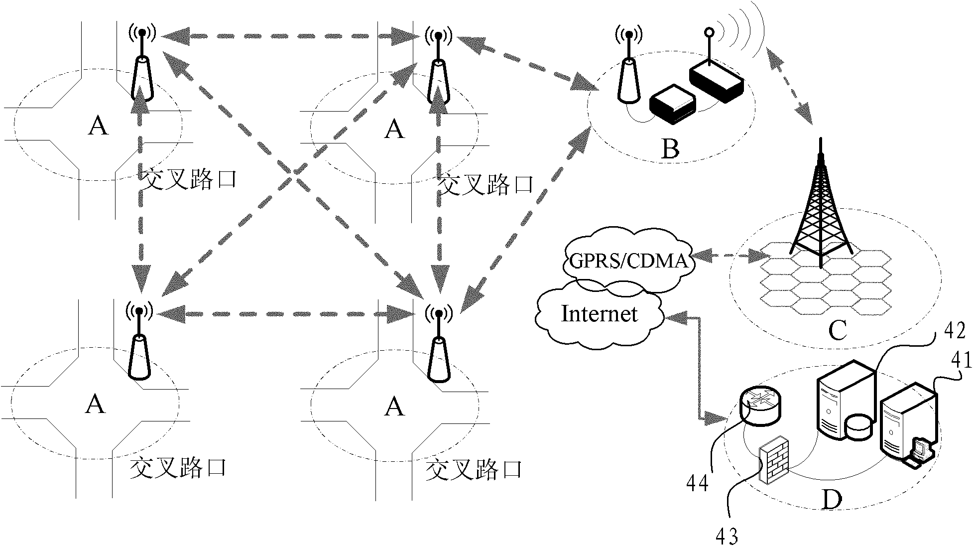
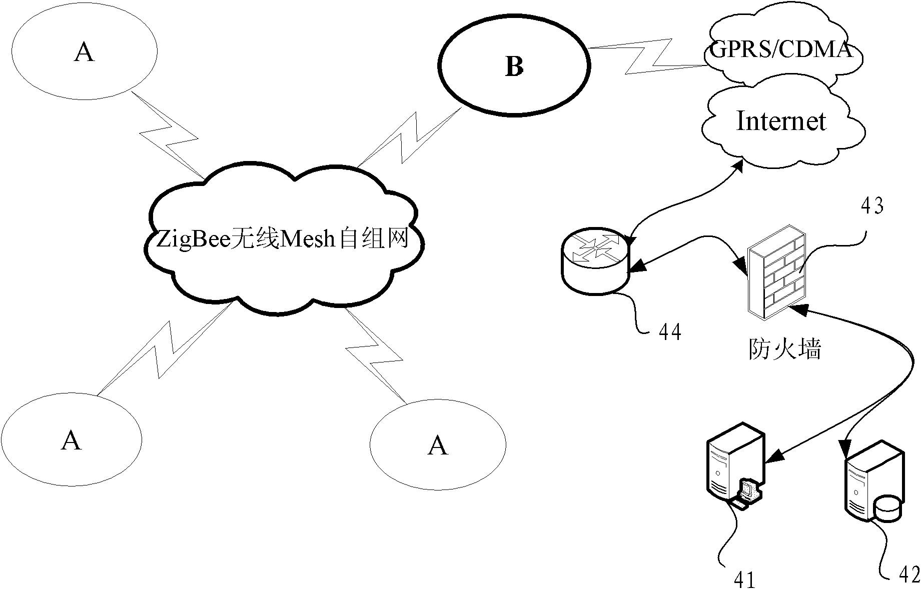
[0131] An intelligent traffic control system based on wireless Mesh ad hoc network, such as figure 1 As shown, the intelligent traffic control system includes: 4 traffic control nodes A, 1 ZigBee regional base station B, mobile communication base station C, and traffic control center D; 4 traffic control nodes A are located at each intersection, inside Each device is connected by RS-232/RS-485 bus. The neighboring nodes use ZigBee technology to realize wireless Mesh ad hoc communication network and exchange traffic data in real time. ZigBee regional base station B and traffic control center D use GPRS through mobile communication base station C /CDMA data transmission equipment for remote connection;
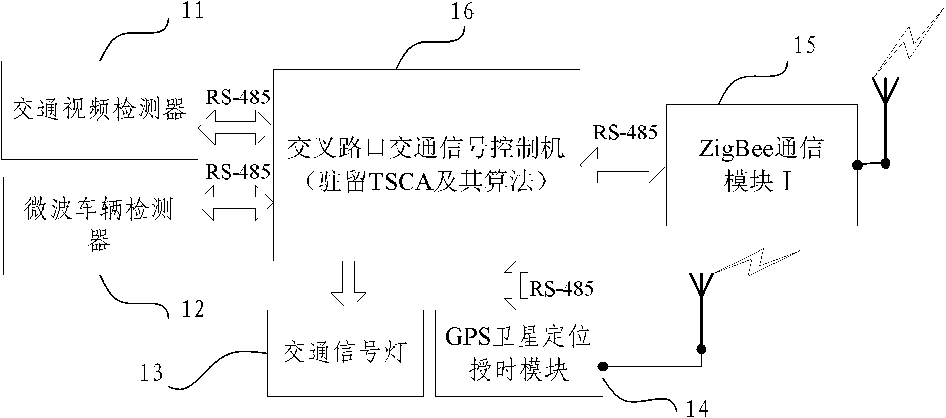
[0132] Such as image 3 As shown, each traffic control node A includes a traffic flow parameter collection device, a traffic signal control device, and a ZigBee communication module I15. The traffic flow parameter collection device includes a traffic flow video detector 11, a traffic microwave vehicle detector 12, and GPS positioning and timing auxiliary device 14; the traffic signal control equipment is the intersection traffic signal control machine 16 and traffic signal indicator light 13 that reside in the TSCA communication protocol and its algorithm. The main functions of the traffic flow parameter collection equipment are:
[0133] The traffic flow video detector 11 is used to obtain the traffic volume, vehicle type, vehicle speed, queue length and various other traffic incident detections of various turns at the intersection, and is suitable for working when the climatic conditions and illumination meet the basic requirements;
[0134] The microwave vehicle detector 12 is used to obtain the traffic flow, vehicle type, and speed of each lane; it is suitable for assistance at night and when the video detector cannot work normally;
[0135] Each traffic control node uses a communication transceiver with embedded ZigBee communication module Ⅰ15 and industrial 485 bus technology to communicate with its own wireless Mesh local communication control network. The traffic signal control agent (TSCA) of each node is based on the BNNC traffic control protocol-traffic Based on the traffic control protocol of the neighbor negotiation mechanism, the control node exchanges the collected intersection traffic flow parameters and signal timing plan data in real time in a small area adjacent to each other, and serves as the decision-making basis for adaptive coordinated control of traffic signals; the specific negotiated area is determined by The associated node and branch parameters in the road network topology are determined, which can be set according to the actual needs of point, line, and area control, and can be of various irregular shapes;
[0136] Each traffic control node A can also aggregate data through the ZigBee regional base station of the Mesh network at the same time, and upload the traffic detection and signal timing control data to the traffic control center D through the GPRS/CDMA data transmission terminal, and the traffic control center D will follow the traffic Data analysis and actual situation needs, download control instructions or optimized adjustment parameters to the wireless Mesh traffic signal control network in real time, and control the network to unconditionally execute the control plan of the center or make configuration parameter adjustments (see figure 2 ).
[0137] Such as Figure 4 As shown, the ZigBee regional base station B includes an ARM processor system 22 based on μClinux operating system, a GPRS/CDMA wireless data transmission communication module 21, and a ZigBee communication module II 23. The ARM processor system 22 and GPRS/CDMA wireless data transmission communication The modules 21 and between the ARM processor system 22 and the ZigBee communication module II 23 are respectively connected by RS-485 bus; the data communication of the ZigBee regional base station B is realized based on the BDAT communication protocol stack, and the ZigBee communication module II 23 is used to receive each traffic control node The signal sent by A, the ARM processor system 22 processes the signal sent by each traffic control node A, and sends it to the traffic control center D through the GPRS/CDMA wireless data transmission communication module 21 and the mobile communication base station C. The GPRS/CDMA wireless data transmission communication module 21 receives the adjustment and optimization parameters or mandatory instructions from the traffic control center D by means of the mobile communication base station C and sends it back to the traffic control nodes via the ZigBee communication module II23.
[0138] The ZigBee module has a built-in CSMA/CA anti-collision mechanism to effectively prevent data loss; it adopts a DSSS spread spectrum mechanism and 16 channels are freely selected to avoid signal interference.
[0139] The traffic control center D includes an application server 41, a database server 42, and a router 44. A firewall 43 is installed between the application server 41 and the router 44, and between the database server 42 and the router 44 of the control center; The central server 41 and the database server 42 both have the function of dual-host failover hot-switching, and run TSCA intelligent traffic control system software based on the Oracle relational database and geographic information system GIS platform; the application server 41 and the database server 42 receive ZigBee regional base stations After processing, the application server 41 and database server 42 will return the data and control information to the ZigBee regional base station B for the on-site data information sent by each traffic control node A of the system after being processed. Control or participate in the decision-making and optimization of the traffic signal timing plan of each traffic control node A (see figure 1 , figure 2 ).
[0140] Such as Figure 5 As shown, the composition of the TSCA communication protocol stack where the intersection traffic signal control machine 16 resides is: the bottom layer is IEEE802.15.4 physical layer PHY, the above are IEEE802.15.4 media access control layer MAC, network layer, 128-bit encryption in order The security layer and application layer interface, the top layer is the TSCA application layer for traffic monitoring and control data exchange.
[0141] Such as Image 6 As shown, the composition of the regional base station BDAT communication protocol stack of the ZigBee regional base station B is: the regional base station application layer for traffic data aggregation and inter-network forwarding is located at the top of the protocol stack, and is divided into two sub-parts, the ZigBee network and the IP network. ; Among them, the bottom layer of the ZigBee network sub-part is IEEE802.15.4 physical layer PHY, the above are the IEEE802.15.4 media access control layer MAC, network layer, 128-bit encrypted security layer and application layer interface; the bottom layer of the IP network sub-part is GPRS/CDMA The physical layer of the wireless network is the PPP data link layer, the IP network layer, and the TCP/UDP transport layer in the upward order.
[0142] Such as Figure 7 As shown, the traffic control node A is based on the traffic control protocol-BNNC traffic control protocol data unit of the neighbor negotiation mechanism, namely: the ZigBee network layer data frame format is: the first layer includes: the network layer frame header, and the data refers to the reference time , Traffic detection data area 1, traffic control data area 2. The second layer includes: detection equipment type, detection parameter 1..., detection parameter p, the third layer includes: signal period, signal phase number q, phase 1 parameter... , The phase q parameter; the value range of p and q is: p and q are any integers between 1 and 100 respectively.
[0143] Embodiment 1 is only one of the preferred embodiments commonly used in the specific implementation of the present invention.
[0144] As a variation of the first embodiment of the present invention, the number of traffic control nodes A can also be increased or decreased, at least 2, or as many as n (A1, A2, A3, A4, A5,... An, for the convenience of description, A1, A2, A3, A4, A5,...An are collectively referred to as A), the general value range of n is: n is any integer between 2, 3, 4, 5...256, As the traffic control node A increases, the number m of base stations B in the ZigBee area increases accordingly. Generally, the value range of m is: m is any integer between 1, 2, 3, 4, 5...100.
[0145] As a variation of the first embodiment of the present invention, the traffic flow parameter collection device of the traffic control node A can use a ground-sensing coil instead of the traffic microwave in addition to the traffic flow video detector 11 and the traffic microwave vehicle detector 12 The vehicle detector 12 is used to obtain the traffic flow, vehicle type, and speed of various turns at the intersection. In a traffic control node A, these three traffic flow parameter collection devices can be installed at the same time for use in different situations, or only one of them can be installed One or two of them.
[0146] As a variation of the first embodiment of the present invention, each traffic control node is independent of the communication transceivers in the first embodiment using the built-in ZigBee communication module I and the industrial 485 bus technology. The self-assembled wireless Mesh local communication control network is also Data aggregation is carried out through ZigBee regional base stations of the Mesh network, and the traffic detection and signal timing control data are uploaded to the traffic control center through the GPRS/CDMA data transmission terminal; it can also be only the embedded ZigBee communication module I and The communication transceiver of the industrial 485 bus technology communicates from the wireless Mesh local communication control network. At this time, the traffic signal control agent of each node is based on the BNNC traffic control protocol-that is, the traffic control node based on the neighboring negotiation mechanism traffic control protocol. The collected intersection traffic flow parameters and signal timing plan data are exchanged in real time in the adjacent small area, and used as the decision-making basis for the adaptive and coordinated control of traffic signals; this situation is generally when the traffic control center of the system loses communication with the wireless MESH network use.

Example Embodiment

[0147] Example two
[0148] A method of using the intelligent traffic control system based on the wireless Mesh ad hoc network described in the first embodiment for intelligent traffic control, which is a method that combines ZigBee short-range wireless communication technology and intelligent network technology to control each node in the system The traffic flow parameter collection and traffic signal control equipment is connected to the Mesh self-organizing network through Zigbee wireless communication, and the control target area is predefined according to the GPS node positioning information and the road network topology (this area can be planned as points and lines according to actual needs. , Planar) and neighboring associated nodes in accordance with the BNNC traffic control protocol-that is, the traffic control node based on the neighboring negotiation mechanism of the traffic control protocol, real-time exchange of traffic flow parameters, signal control parameters and negotiate the control of each traffic signal control node In decision-making, the TSCA signal control negotiation mechanism of the system adopts a combination of explicit coordination based on game theory and implicit coordination based on knowledge rules; ZigBee regional base stations are based on the BDAT communication protocol stack, and the GPRS/CDMA data transmission terminal combines the Traffic detection and signal control data are uploaded to the traffic control center; the traffic control center downloads some adjustment and optimization parameters or compulsory instructions to each control node to participate in specific intersection signal timing decisions when necessary intervention; system traffic signal coordination control station The required synchronization clock is calibrated independently by the GPS timing module of each node.
[0149] The intelligent traffic control system based on the wireless Mesh ad hoc network of the present invention is used in the method for intelligent traffic control. The control decision of each traffic signal control node includes: the intersection traffic light timing scheme, based on the traffic flow exchanged by neighboring associated nodes in real time Parameters, semaphore control parameters and stored road network topology, historical traffic flow parameters and traffic control data, as well as the central control center's command weighted to make new signal control parameters.
[0150] The method for intelligent traffic control of the intelligent traffic control system based on the wireless Mesh ad hoc network of the present invention includes two components, one is the "neighboring negotiation node search and control node related sub-road network topology establishment algorithm" which establishes the basis of communication between nodes. The other is the "small area self-coordinating traffic signal control algorithm" based on the "neighboring negotiation node search and control node related sub-road network topology establishment algorithm".
[0151] (1) The basic steps of the algorithm of "neighboring negotiation node search and control node related sub-road network topology establishment":
[0152] M1: After the system nodes are powered on, self-check and initialize, and check whether they can work normally, if they can't work normally, go to M2, otherwise go to M3;
[0153] M2: Check if you can work offline, if not, go to M21, if you can work independently offline, go to M22;
[0154] M21: End of node work;
[0155] M22: Work independently according to experience knowledge or pre-stored timing plan;
[0156] M3: Join the Zigbee network to obtain the Zigbee short address, and request a copy of the regional road network topology data from neighboring nodes, including the GPS position, serial number, right of way level, turn and the association between all nodes and branches or sections of the area Parameters, go to M4;
[0157] M4: Receive local node positioning information from GPS satellite positioning module;
[0158] M5: Retrieve the location of the node in the road network topology map according to the positioning information. If the node cannot match any node in the road network topology map, switch to M22 to work independently according to experience knowledge or pre-stored timing scheme, otherwise switch to M6 to continue carried out;
[0159] M51: During the normal operation of the system, if the node receives the control center road network topology update notification, the node workflow unconditionally jumps to M5 and re-executes in sequence;
[0160] M6: Generate the inactive sub-road network topology map associated with this node, find the nodes and branches associated with this node according to the definition of the regional road network topology map, and trim the regional road network topology into the inactive sub-road network associated with this node The topology diagram of the sub-road network is transferred to M7 for execution;
[0161] M61: During the normal operation of the system, if the short address of the node ZigBee network reorganization changes, the node workflow unconditionally jumps to M6 and re-executes in sequence;
[0162] M7: Check whether the associated sub-road network topology exists. If it does not exist, switch to M22 to work independently based on empirical knowledge or pre-stored timing plan. If it exists, create 6 parallel subtasks S1, S2, S3, S4, S5 and S6 to execute simultaneously;
[0163] ①The execution steps of subtask S1:
[0164] S11: Listen to whether the associated node responds to the broadcast datagram that the node is working online, if it does, enter S12, if it does not return to S11, continue to listen;
[0165] S12: Extract the associated node information from the received datagram and verify the existence of the node in the associated sub-road network topology, if it exists, go to S13, otherwise return to S11 to continue the interception;
[0166] S13: After activating the status of the associated node and branch corresponding to the sub-road network, return to S11 to continue listening;
[0167] ②The execution steps of subtask S2:
[0168] S21: Listen to the online working broadcast datagram of the road network node, and transfer to S22 if received, otherwise return to S21 to continue the interception;
[0169] S22: Extract the node information from the received datagram and retrieve the node in the associated sub-road network topology, if it exists, go to S23, otherwise return to S21 to continue the interception;
[0170] S23: Determine whether the node status has been activated, if it is not activated, go to S241, if it is activated, go to S242;
[0171] S241: Activate the corresponding node and branch in the sub-road network topology, and record the corresponding parameters such as its communication address, and at the same time send an online response with the source address of the datagram as the target address and transfer it back to S21 for execution;
[0172] S242: Check whether the relevant parameters of the node need to be updated, if it needs to be updated, switch to S25, otherwise switch to S21;
[0173] S25: Update the relevant parameters of the corresponding node and branch in the sub-road network topology and then return to S21 for execution;
[0174] ③The execution steps of subtask S3:
[0175] S31: Search and check the status of each associated node in the sub-road network topology diagram of the node one by one;
[0176] S32: If an associated node is not in the active state, switch to S31 to continue the judgment of the next node, otherwise switch to S33;
[0177] S33: Regularly send an online heartbeat packet representing the normal operation of the node to the active state node, so that it can maintain its associated sub-road network topology online node list, and provide a basis for normal traffic signal negotiation and control between nodes, and then return to S31 to continue The judgment of the next node;
[0178] ④ Steps for subtask S4:
[0179] S41: Detect the receiving status of the heartbeat packets of each associated node in the sub-road network topology map, and determine whether there is an associated node stoppage, that is, the offline communication connection is lost, and if so, go to S42;
[0180] S42: Change the status of the node and related branches in the sub-road network topology to invalid, and switch to S41 to continue;
[0181] ⑤ Execution steps of subtask S5:
[0182] S51: Listen to whether there is a neighboring node requesting this node to copy the topological graph data of the road network in this area, if yes, go to S52;
[0183] S52: Determine whether there is a copy of the regional road network topology map at this node, and continue without going to S51, if there is, go to S53;
[0184] S53: Send the relevant data of the regional road network topology to the requester, then transfer to S51 to continue;
[0185] ⑥ Steps for subtask S6:
[0186] S61: Search for the status of each associated node in the sub-road network topology map, and go to S62;
[0187] S62: If an inactive node is found, go to S63, if not, go to S61;
[0188] S63: Regularly broadcast to announce that the node has been online and work, then transfer to S61 to continue execution.
[0189] (2) The basic steps of "Small Area Self-coordination Traffic Signal Control Algorithm" are:
[0190] The control algorithm is divided into 4 parallel subtasks T1, T2, T3 and T4, which are executed simultaneously:
[0191] ① The execution steps of subtask T1:
[0192] T11: Listen to the working datagram sent by the associated node of the sub-road network and save it;
[0193] T12: Check whether the current traffic signal control cycle of this node is about to end, if not, turn to T11, otherwise turn to T13;
[0194] T13: Obtain the traffic detection data of this node, as well as the traffic flow parameters of the associated nodes in the sub-road network topology and the corresponding timing plan. According to the control model algorithm and the needs of "point, line, surface" control, determine whether it needs to be adjacent to the relevant The node performs coordinated control. If it is not needed, it will go to T14 directly. If it needs coordinated control, it will go to T131 for execution;
[0195] T131: Send a negotiation request and execute the corresponding coordination process within the specified time, agree on the control parameters, and then transfer to T14;
[0196] T14: Substitute the corresponding parameters determined in the above steps into the control model to obtain the current signal control cycle data of this node, and set and execute various timing parameters of the signal control machine of this node, and go to T15;
[0197] T15: Read the local synchronization clock, send the signal timing plan datagram with the synchronization time stamp of the node to each active node of the sub-road network and the regional base station, and then transfer back to T11 to continue execution;
[0198] ② The execution steps of subtask T2:
[0199] T21: Judge whether the calibration period of the local synchronization clock has arrived, if so, turn to T22;
[0200] T22: Read the GPS module timing information to synchronize the local clock, go to T21 to continue execution;
[0201] ③ The execution steps of subtask T3:
[0202] T31: Determine whether the local traffic flow detection data sending cycle has come, if it has come, turn to T32;
[0203] T32: Read the local synchronous clock, and send traffic flow data of this node to each active node of the sub-road network and regional base stations; go to T31 to continue execution;
[0204] ④ Execution steps of subtask T4:
[0205] T41: Listen to whether there is an associated node requesting a coordinated control message, and if so, forward to T42;
[0206] T42: Decide whether to accept the coordinated control request according to the current control strategy and traffic conditions of the node. If rejected, transfer to T421 for execution, and if agreed, transfer to T43 for execution;
[0207] T421: Send a refusing coordination message to the requesting party, transfer to T41 to continue;
[0208] T43: Check whether there is a suitable knowledge rule, if there is, transfer to T431 for execution, if not, transfer to T432 for execution;
[0209] T431: Select rules and determine the corresponding control strategy according to the rules, then transfer to T44;
[0210] T432: Seek the optimal solution for coordination, determine the control strategy of both parties, and transfer to T44;
[0211] T44: Draw various coordinated control parameters into the control decision-making link, and then return to T41 to continue execution.
[0212] In the method for intelligent traffic control of the intelligent traffic control system based on the wireless Mesh ad hoc network of the present invention, the TSCA signal control negotiation mechanism of the system is composed of the TSCA communication protocol stack, and the ZigBee regional base station is based on the BDAT communication protocol stack. The composition and the data unit of the traffic control protocol-BNNC traffic control protocol based on the neighbor negotiation mechanism of the traffic control node, namely: the ZigBee network layer data frame format has been described in detail in the first embodiment, and will not be repeated here.

PUM

no PUM

Description & Claims & Application Information

We can also present the details of the Description, Claims and Application information to help users get a comprehensive understanding of the technical details of the patent, such as background art, summary of invention, brief description of drawings, description of embodiments, and other original content. On the other hand, users can also determine the specific scope of protection of the technology through the list of claims; as well as understand the changes in the life cycle of the technology with the presentation of the patent timeline. Login to view more.

Similar technology patents

Integrated embedded pipe hot stamping die for automobile parts

InactiveCN102029310AManufacturing process cycle and cost reductionThe overall structure is simpleShaping toolsMotor vehicle partHot stamping
Owner:BAOSHAN IRON & STEEL CO LTD

Classification and recommendation of technical efficacy words

  • The overall structure is simple
  • Reduce power consumption

Time frequency analysis based loudspeaker noise online detecting instrument

InactiveCN101115329AThe overall structure is simpleLow installation and manufacturing costsElectrical apparatusTime–frequency analysisLoudspeaker
Owner:TIANJIN UNIVERSITY OF SCIENCE AND TECHNOLOGY +1

Semiconductor integrated circuit device and method of manufacturing the same

ActiveUS20060113520A1Extend kindReduce power consumptionSolid-state devicesBulk negative resistance effect devicesIntegrated circuitOxide
Owner:RENESAS ELECTRONICS CORP
Why Eureka
Try Eureka