Sewage recycling system for concrete stirring station

A technology of sewage recycling and mixing station, which is applied in the directions of water/sewage multi-stage treatment, water/sludge/sewage treatment, centrifuged water/sewage treatment, etc. It can solve the problems of natural environment pollution, reduce waste of resources, reduce The effect of production cost, easy installation and use

Inactive Publication Date: 2017-07-25
郑州新水工机械有限公司
1 Cites 12 Cited by

AI-Extracted Technical Summary

Problems solved by technology

[0002] During the production and operation of the concrete mixing station, a large amount of sewage will inevitably be generated due to cleaning of mixers, tank trucks, pump trucks and other equipment. This sewage not only ...

Method used

Concrete mixing plant sewage recycling system of the present invention can fully clean the entrapped in sewage by sand-stone separator, sand-water separation device, cyclone desander, mortar tank, grit chamber and water storage adjustment tank The sand and gravel are separated and classified and recycled, and the separated water can be recycled and reused through the concentration adjustme...

Abstract

The invention discloses a sewage recycling system for a concrete stirring station. According to the sewage recycling system, sewage is cleaned by virtue of water collection tank gathering equipment and flows through a sandstone separation machine, a sand-water separation device, a mortar tank, a sand settlement tank and a storage water regulating tank, and then sandstone mixed in the sewage can be sorted and recycled, and furthermore, treated sewage is subjected to concentration regulation through the storage water regulating tank and can be recycled; and the sewage recycling system for the concrete stirring station is simple in structure and convenient to mount and use, the cycling and reutilization of cleaning wastewater of the stirring station are realized, the zero-emission of wastewater is achieved, the wasting of resources is reduced, and meanwhile, the production cost of the concrete stirring station is lowered.

Application Domain

Technology Topic

Image

  • Sewage recycling system for concrete stirring station

Examples

  • Experimental program(1)

Example Embodiment

[0013] The sewage recycling system of the concrete mixing plant of the present invention will be described in detail below with reference to the accompanying drawings.
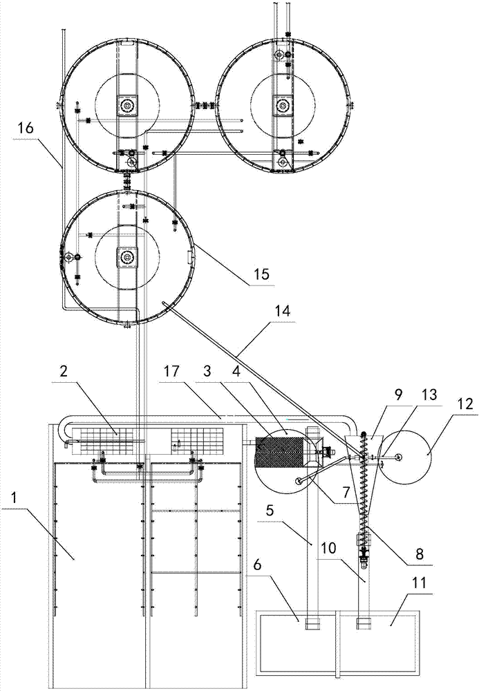
[0014] Such as figure 1 As shown, the sewage recycling system of the concrete mixing plant of the present invention is mainly composed of a water collection tank 2, a sand-gravel separator 3, a sand-water separation device 8, a mortar tank 4, a grit chamber 12, and a water storage regulating tank 15. , The inlet of the sump 2 collects sewage from the cleaning equipment of the concrete mixing plant, and the outlet of the sump 2 is connected to the gravel separator 3. In this embodiment, the inlet of the sump 2 is connected to the car wash point 1 in the mixing station through a sewer . The sand-gravel separator 3 is provided with a feed tank connected to the outlet of the water collection tank 2 and a stone outlet and a mortar outlet that output large stones and sand-water mixed slurry after separation. The stone outlet of the sand-gravel separator 3 is conveyed by the stone The machine 5 is connected to the stone recovery bin 6, the mortar outlet of the sand and gravel separator 3 is connected to the mortar pool 4, and the perforated rolling screen with better separation effect is installed in the sand and gravel separator 3, which combines drum separation and spiral screening The feature of type separation can automatically complete the separation of sand, stone and slurry water in the cleaning sewage. Larger stones and gravel are discharged from the stone outlet and fall on the stone conveyor 5 and are sent to the stone recovery bin 6, which can be reused , The finer sand and gravel mixed slurry water flows into the mortar pool 4 through the mortar outlet. In this embodiment, the sand and gravel separator 3 is straddled on the mouth of the mortar pool 4 through the equipment bracket, and there is no need to install additional pipes. Gravity can be used to allow slurry water to flow into the mortar tank 4 through the mortar outlet at the bottom of the sand-gravel separator 3. The sand-water separation device 8 adopts a conventional spiral sand-water separator. This spiral sand-water separator is provided with a feed box 9 which is connected to the sand discharge port through an inclined shaftless screw and enters The material box 9 is provided with an overflow port, and a sand conveyor 10 is provided under the sand discharge port of the spiral sand-water separator. The sand conveyor 10 is connected to the sand recovery bin 11, and the mortar tank 4 is connected in series. A conveying pipe with a mortar pump is connected to the feed box 9 of the sand-water separation device 8. A level gauge is installed in the mortar tank 4. When the slurry water in the mortar tank 4 is at a high level, the mortar pump starts to pump the mortar into the spiral The sedimentation in the feed box 9 of the sand-water separator, after sedimentation, the upper water flows from the overflow port through the overflow pipe into the grit tank 12 for further precipitation, and the fine gravel deposited on the bottom of the feed box 9 is removed from the sand tank through the shaftless spiral The sand discharge port discharges and falls on the sand conveyor 10 and is sent to the sand recovery bin 11 to realize the recovery and reuse of sand. An overflow return pipe 17 is also connected to the feed box 9 of the spiral sand-water separator. The overflow return pipe 17 is connected to the inlet of the sump 2 to increase the water flow impulse in the sump 2 and realize the opposite collection. Wash the bottom of the sink 2 to avoid the sand and stones mixed in the cleaning sewage from staying in the sink 2. A cyclone desander (not shown in the figure) is also provided above the feed box 9 of the spiral sand-water separator. The upper water inlet of the cyclone desander is connected to the grit chamber 12 through a pipe. The water outlet on the top of the cyclone desander is connected to the water storage adjustment tank 15 through a pipe, and the sewage outlet at the bottom of the cyclone desander directly faces the feed box 9 of the spiral sand-water separator, in the grit chamber 12 There is also a level gauge. When the liquid level in the grit tank 12 is at a high level, the water pump starts to pump the water in the mortar tank 4 into the cyclone desander to further complete the separation of sand and water. The bottom drain outlet falls into the feed box 9, and is discharged from the sand outlet via the shaftless screw after precipitation, and the separated water is sent to the water storage regulating tank 15 through the pipeline. There are three water storage adjustment tanks 15 in this embodiment, and the three water storage adjustment tanks 15 are connected to each other through a butt pipe. The water storage adjustment tank 15 is equipped with a concentration meter and is connected with a clean water pipe 16, which can According to the concentration of sewage in the tank detected by the concentration meter, clean water is added to adjust, so that the concentration of sewage stored in the tank reaches the use index in the mixing station, and the recycling and reuse of water resources is realized. In order to further reduce the concentration of sewage in the tank, a sewage outlet is also provided at the bottom of the water storage regulating tank 15. The fine sand particles contained in the sewage entering the water storage regulating tank 15 settle on the bottom of the tank and can pass through at regular intervals. The sewage pipe connected to the sewage outlet sends the settled fine sand particles back to the grit tank 12 for recirculation, which improves the recovery and reuse effect of the gravel.
[0015] The sewage recycling system of the concrete mixing plant of the present invention can fully separate the sand and gravel contained in the cleaning sewage through the sand and gravel separator, the sand and water separation device, the cyclone desander, the mortar tank, the grit tank, and the water storage adjustment tank. It is classified and recycled, and the separated water can be recycled and reused through the concentration adjustment of the water storage adjustment tank. The overall structure of the sewage recycling system of the concrete mixing plant is simple, easy to install and use, and the recycling of the cleaning wastewater of the mixing plant is realized. The zero discharge of wastewater is achieved, which not only reduces the waste of resources, but also reduces the production cost of the concrete mixing plant.

PUM

no PUM

Description & Claims & Application Information

We can also present the details of the Description, Claims and Application information to help users get a comprehensive understanding of the technical details of the patent, such as background art, summary of invention, brief description of drawings, description of embodiments, and other original content. On the other hand, users can also determine the specific scope of protection of the technology through the list of claims; as well as understand the changes in the life cycle of the technology with the presentation of the patent timeline. Login to view more.

Similar technology patents

Integrated embedded pipe hot stamping die for automobile parts

InactiveCN102029310AManufacturing process cycle and cost reductionThe overall structure is simpleShaping toolsMotor vehicle partHot stamping
Owner:BAOSHAN IRON & STEEL CO LTD

Classification and recommendation of technical efficacy words

  • The overall structure is simple
  • Easy to install and use

Time frequency analysis based loudspeaker noise online detecting instrument

InactiveCN101115329AThe overall structure is simpleLow installation and manufacturing costsElectrical apparatusTime–frequency analysisLoudspeaker
Owner:TIANJIN UNIVERSITY OF SCIENCE AND TECHNOLOGY +1

Rise up table top

Owner:WEST VIRGIL J +1
Why Eureka
Try Eureka