
Waste organic glass continuous cracking device

A technology of plexiglass and cracking device, applied in the field of waste plexiglass continuous cracking device, can solve the problems of waste of cracking resources, high production cost, easy to cause accidents, etc., and achieve the effect of simple overall structure, control of production cost, and improvement of safety performance.

Active Publication Date: 2010-10-20
TAIXING TOMSON ACRYLIC CO LTD
View PDF0 Cites 12 Cited by
  • Summary
  • Abstract
  • Description
  • Claims
  • Application Information

AI Technical Summary

Problems solved by technology

The traditionally used cracking furnace is mainly fed from the storage bin to the cracking bin, and is directly collected from the cooling bin after being cracked by the cracking bin. This structure can complete the whole process of resource cracking and recovery, but the gas pressure of the material in the cracking furnace after gasification Larger, if there is no safety protection device, once there is a partial failure in the cracking furnace or the air pressure is too high, it will easily cause an accident and pose a safety hazard; even if a simple pressure relief device is installed on the cracking furnace, the safety performance will be improved to a certain extent, but in Pressure relief also wastes most of the pyrolysis resources, resulting in low product yield and high production costs. In addition, the gas discharged from pressure relief is likely to cause environmental pollution

Method used


Image

  • Waste organic glass continuous cracking device
  • Waste organic glass continuous cracking device
  • Waste organic glass continuous cracking device

Examples


Embodiment Construction

[0013] The present invention will be further described below in conjunction with drawings and embodiments.

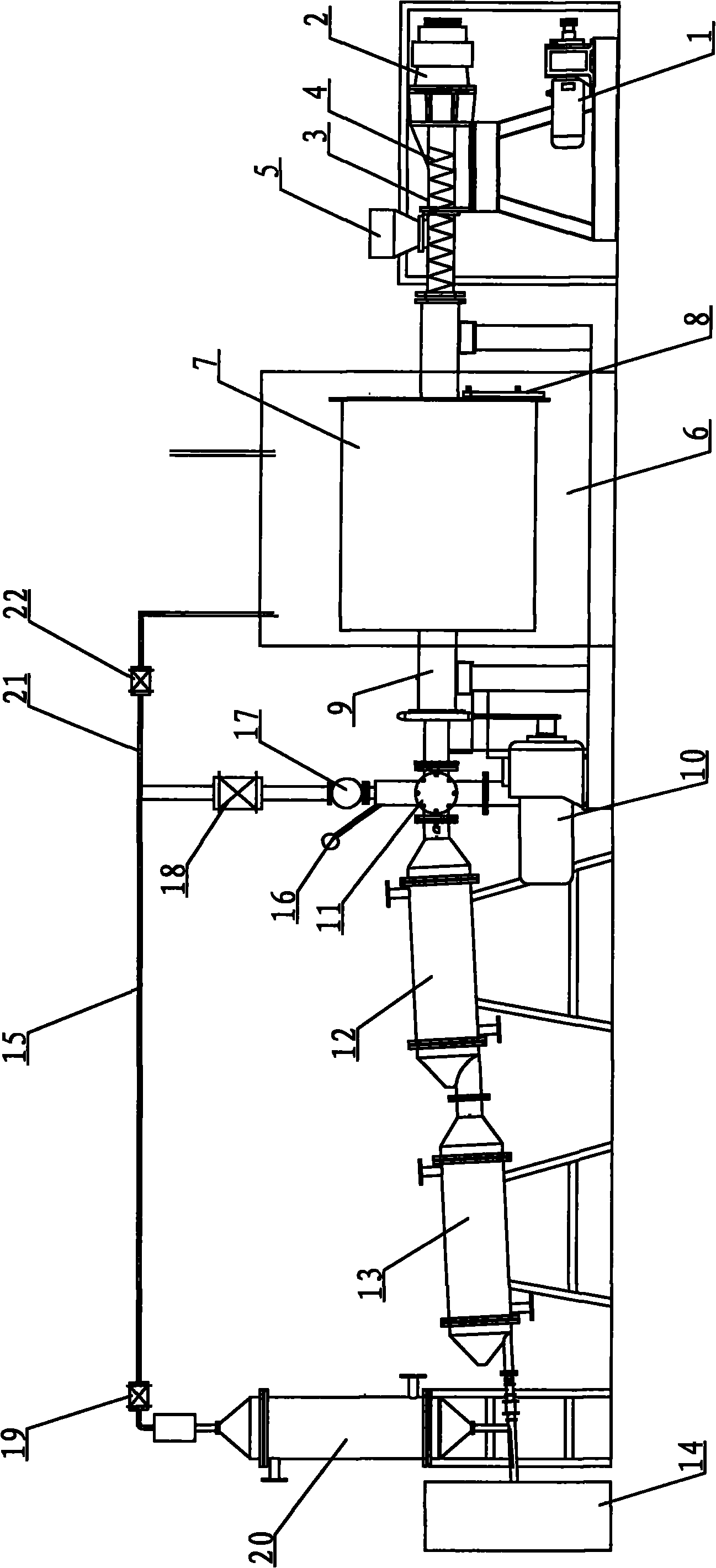
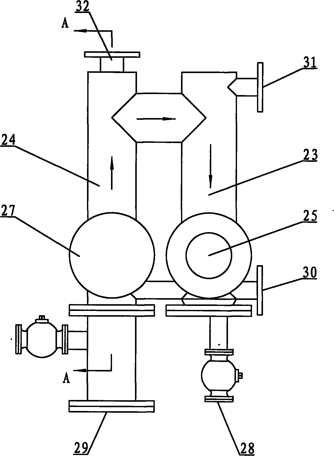
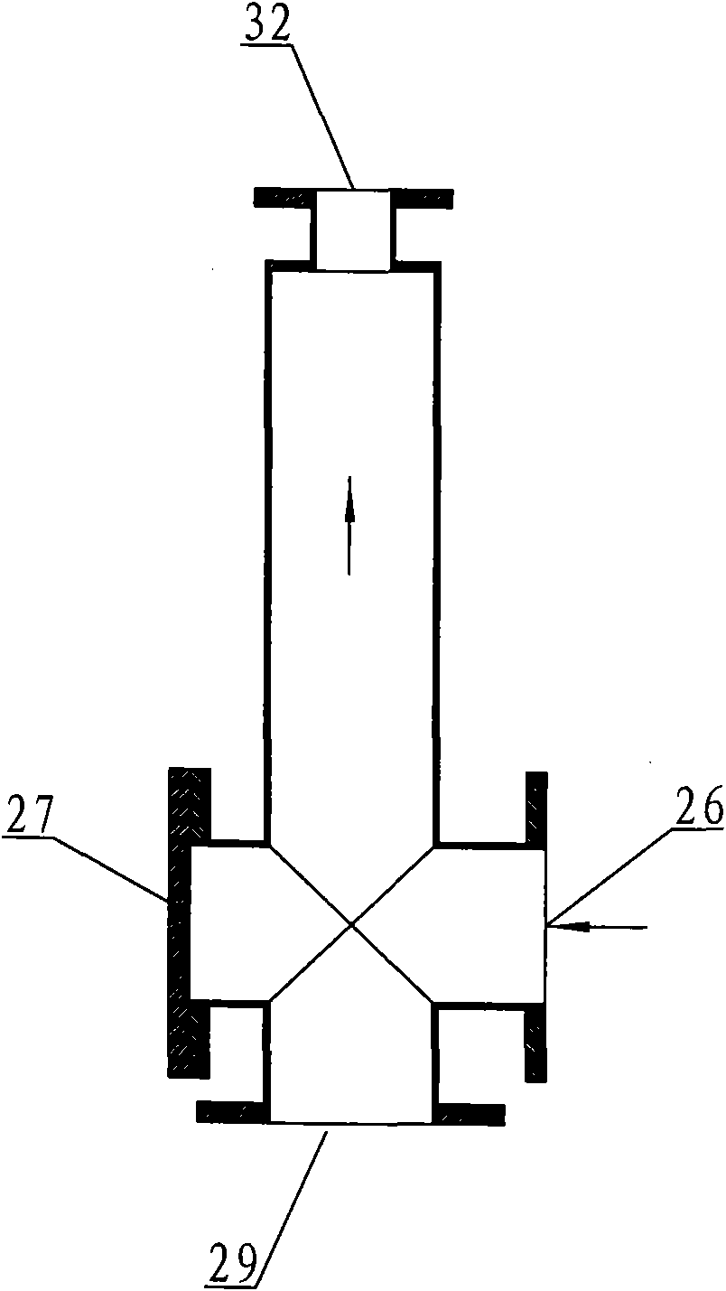
[0014] figure 1 The waste plexiglass continuous cracking device shown mainly includes a feeding device, a melting furnace and a storage tank 14 . The feeding device includes a hopper 5, a feeding pipe 3, a feeding screw 4, a reducer 2 and a feeding motor 1, one end of the feeding pipe 3 is provided with a reducer 2 connected to the feeding motor 1, and the other end of the feeding pipe 3 is connected to In a hot melting furnace, a feeding screw 4 is arranged in the feeding pipe 3, and the feeding screw 4 is connected to the reducer 2, and the feeding pipe 3 is provided with a hopper 5 located above the feeding screw 4; the hot melting furnace includes a furnace body 7, a rotating motor 10 and the incineration chamber 6, the side of the furnace body 7 is provided with a slag outlet 8, the furnace body 7 is placed in the incineration chamber 6, one end of the furnace bod...


PUM


Abstract

The invention relates to a waste organic glass continuous cracking device mainly comprising a feeding device, a hot melt furnace, a solid and gas separator, a condenser and a storage tank which are all connected sequentially, wherein the solid and gas separator is also provided with a safety pipeline; a pressure gauge, a safety valve and a three-stage condenser are sequentially arranged on the safety pipeline; an outlet of the three-stage condenser is connected to the storage tank; the safety pipeline between the safety valve and the three-stage condenser is provided with a pressure relief pipeline; and an outlet of the pressure relief pipeline is connected to an incinerating chamber. The solid and gas separator of a discharging pipeline is additionally provided with the safety pipeline which is provided with the pressure relief pipeline, a high-pressure gas branch in the cracking furnace is condensed and liquefied by the discharging pipeline and the safety pipeline, and the safe use of the cracking furnace is ensured by the pressure relief pipeline. The integral structure is simple, the safety property is high, the product yield rate is high, the production cost can be effectively controlled, and the invention has no environment pollution in the cracking process.

Description

technical field [0001] The invention relates to a cracking furnace, in particular to a waste organic glass continuous cracking device for preparing organic glass pouring raw materials. Background technique [0002] Pyrolysis technology is one of the important means to recover and reuse various resources in the chemical industry, and cracking furnaces are often used for cracking and recycling. The traditionally used cracking furnace is mainly fed from the storage bin to the cracking bin, and is directly collected from the cooling bin after being cracked by the cracking bin. This structure can complete the whole process of resource cracking and recovery, but the gas pressure of the material in the cracking furnace after gasification Larger, if there is no safety protection device, once there is a partial failure in the cracking furnace or the air pressure is too high, it will easily cause an accident and pose a safety hazard; even if a simple pressure relief device is installe...

Claims


Application Information

Patent Timeline
IPC IPC(8): C08J11/12C08L33/12
CPCY02W30/62
Inventor 汤月生季一岷
Owner TAIXING TOMSON ACRYLIC CO LTD
Learn More