Balancing device and crane with same

A technology of balancing device and crane, which is applied to cranes and other directions, can solve problems such as crane overturning accidents, achieve the effects of reducing accident losses, overcoming overturning accidents, and improving safety performance

Inactive Publication Date: 2011-04-20
SANY AUTOMOBILE HOISTING MACHINERY
5 Cites 19 Cited by

AI-Extracted Technical Summary

Problems solved by technology

[0003] The present invention aims to provide a balancing device and a crane including the balancing d...

Method used

Preferably, hydraulic oil cylinder 3 is arranged on the outside of guide rail 42 in parallel, and connects mobile counterweight device 4 by transverse connection structure, because hydraulic oil cylinder 3 is not arranged on the motion track of mobile counterweight device 4, therefore, does not It will affect the movement of the mobile counterweight device 4, and at the same time can increase its movement stroke and expand its adjustment range.
Referring to Fig. 2 and Fig. 3, have shown the structure according to the first embodiment that balancing device of the present invention is applied to crane, in this embodiment, mobile counterweight device 4 comprises: guide rail 42 and guide rail 42 phase The matching mobile counterweight 41 has a groove structure matched with the guide rail 42 . For example, the guide rail 42 is arranged on the installation platform (turntable) 5 for easy installation, and its extension direction is perpendicular to the traveling direction of the crane, so that the moving direction of the mobile counterweight 41 is also perpendicular to the traveling direction of the crane. Because the possibility of the crane rolling over is relatively large, it is only necessary to make the mobile counterweight 41 move in a direction perpendicular to the traveling direction of the crane. The block 41 moves towards the direction opposite to the inclination direction of the crane body under the action of the execution structure 3, so that the mobile counterweight 41 produces a force opposite to the inclination direction of the car body, so that the crane is kept balanced and rollover is not easy to occur. Preferably, the horizontal angle sensor 1 is arranged on the installation platform 5 and parallel to the guide rail 42, so as to accurately sense the inclination angle of the crane.
Referring to Fig. 4, has shown the structure according to the second embodiment of balancing device of the present invention, and the difference with above-mentioned first embodiment is that mobile counterweight 41 is directly arranged on the installation platform and is positioned at installation Above the platform 5, a rolling member 7 is set between the mobile counterweight 41 and the installation platform 5, so that the mobile counterweight 41 and the installation platform 5 are in a rolling fit relationship. Preferably, the rolling member 7 is a roller or a ball arranged on the moving counter...

Abstract

The invention provides a balancing device, which comprises a movable counterweight device, a drive mechanism, an induction device and a controller, wherein the movable counterweight device is arranged on a vehicle body, and is provided with a movable counterweight block; the drive mechanism is in drive connection with the movable counterweight block; the induction device is used for measuring the tilting angle of the vehicle body; and the controller is in signal connection with the induction device, judges the tilting direction of the vehicle body according to the tilting angle and controls the drive mechanism to act to drive the movable counterweight block to move towards a direction opposite to the tilting direction of the crane. The invention also discloses the crane with the balancing device. The balancing device provided by the invention can effectively ensure the stability of the crane in a running process and reduce the occurrence of overturning accidents.

Application Domain

Technology Topic

Image

  • Balancing device and crane with same
  • Balancing device and crane with same
  • Balancing device and crane with same

Examples

  • Experimental program(1)

Example Embodiment

[0019] It should be noted that, in the case of no conflict, the embodiments in the present application and the features in the embodiments can be combined with each other. The present invention will be described in detail below with reference to the accompanying drawings and examples.
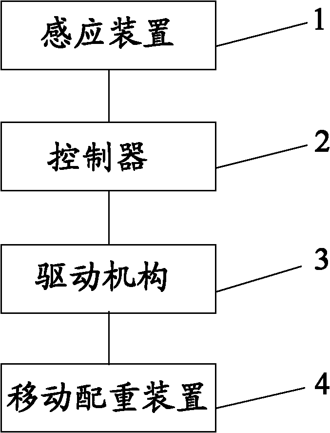
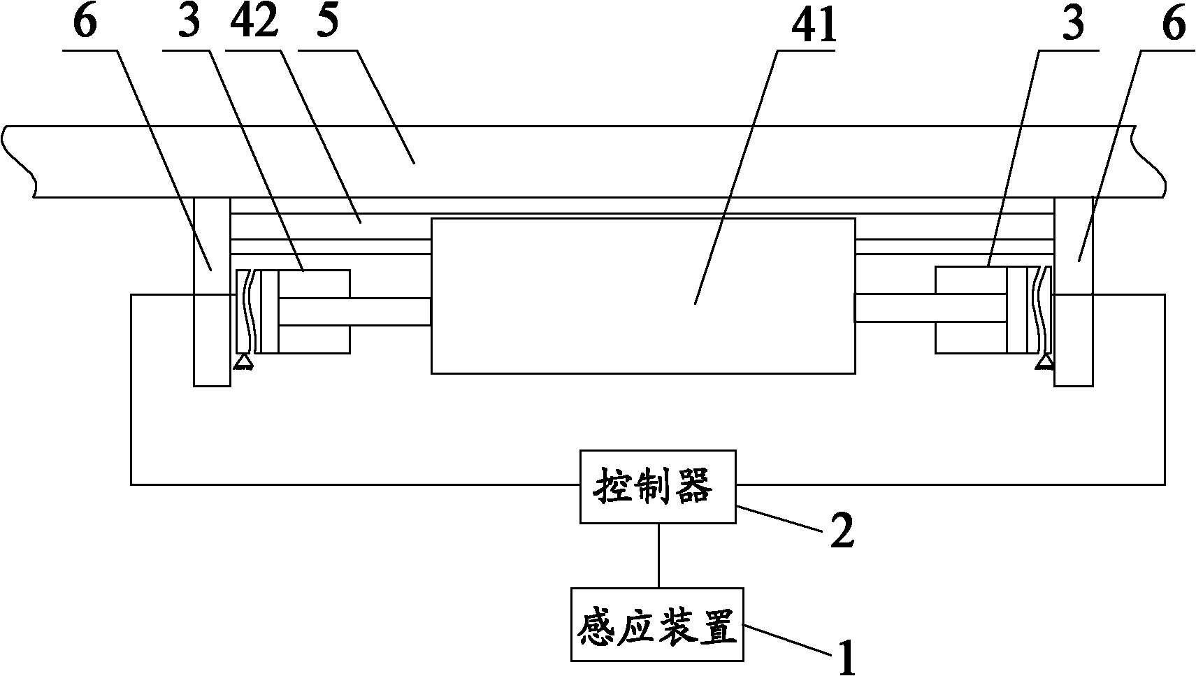
[0020] see figure 1 , shows a flow chart of the principle of a balancing device according to the present invention, as shown in the figure, the balancing device includes: a mobile counterweight device 4, which is arranged on the car body of the crane, and has a mobile counterweight 41 which is movable The driving mechanism 3 is driven and connected with the mobile counterweight 41; the sensing device 1, for example, the sensing device 1 is a horizontal angle sensor, which can sense the inclination angle of the crane; the controller 2 is connected with the sensing device signal, and the receiving sensing device 1 sends out Determine the tilt direction of the crane and send a control signal to the drive mechanism 3 to control the action of the drive mechanism 3, so that the drive mechanism 3 drives the mobile counterweight 41 to move in a direction opposite to the tilt direction of the crane.
[0021] see figure 2 and image 3 , shows the structure of the first embodiment in which the balancing device according to the present invention is applied to a crane. In this embodiment, the mobile counterweight device 4 includes: a guide rail 42 and a mobile counterweight 41 matched with the guide rail 42. The counterweight 41 has a groove structure matched with the guide rail 42 . For example, the guide rail 42 is arranged on the installation platform (turntable) 5 for easy installation, and its extension direction is perpendicular to the traveling direction of the crane, so that the moving direction of the mobile counterweight 41 is also perpendicular to the traveling direction of the crane. Because the possibility of the crane rolling over is relatively large, it is only necessary to make the mobile counterweight 41 move in a direction perpendicular to the traveling direction of the crane. The block 41 moves towards the direction opposite to the inclination direction of the crane body under the action of the execution structure 3, so that the mobile counterweight 41 produces a force opposite to the inclination direction of the car body, so that the crane is kept balanced and rollover is not easy to occur. Preferably, the horizontal angle sensor 1 is arranged on the installation platform 5 and parallel to the guide rail 42, so as to accurately sense the inclination angle of the crane.
[0022] The driving mechanism 3 is further a hydraulic cylinder with a servo valve, which is arranged on a fixed fulcrum outside at least one side of the guide rail 42. For example, the cylinder end of the hydraulic cylinder 3 is fixed on the above-mentioned fixed fulcrum, and the piston rod of the hydraulic cylinder is End is connected with mobile counterweight 41. According to the control signal sent by the controller 2, the hydraulic cylinder 3 has its non-rod cavity and rod cavity in the opposite state of oil in and out, prompting its piston rod to perform corresponding telescopic movements, thereby driving the moving counterweight 41 to move. This control method The structure is simple, convenient and effective. Of course, if figure 2 As shown in , the hydraulic cylinders 3 can be arranged on both sides of the guide rail 42, and the outer ends of the piston rods of the two hydraulic cylinders 3 are respectively connected to the mobile counterweight 41, so that the movement of the mobile counterweight 41 is smoother and more reliable. , and when one of the hydraulic cylinders fails, the other hydraulic cylinder can also effectively control the movement of the mobile counterweight 41, ensuring reliable operation of the balancing device.
[0023] Preferably, in order to increase the safety performance of the mobile counterweight, a stop protection structure 6 is also provided at both ends of the guide rail, for example, a stop plate 6 arranged at both ends of the guide rail 42 to prevent accidental slipping of the mobile counterweight 41 cause safety accidents. As long as the stop plate reaches the sealing at both ends of the groove that makes the guide rail and the mobile counterweight match, or as shown in the figure, the height of the stop plate is higher, and the whole body of the mobile counterweight 41 can also be stopped. block.
[0024] It is easy to understand that in an unshown embodiment, according to the balancing device of the present invention, the guide rail 42 can also be arranged in a rectangular shape on the installation platform 5, and the four sides of the rectangular guide rail are provided with movable counterweights 41, and Drive the drive mechanism 3 of the mobile counterweight, and the four sections of guide rails corresponding to the four sides all have horizontal angle sensors 1 arranged in parallel with it, and each horizontal angle sensor 1 is respectively connected with the controller 2 to control the corresponding mobile configuration. The movement of the weight 41 makes the mobile counterweight 41 always move in the opposite direction to the shaking of the car body, so as to keep the balance of the whole vehicle of the crane and achieve a better effect of preventing the crane from tipping over.
[0025] Preferably, the hydraulic cylinder 3 is arranged in parallel on the outside of the guide rail 42, and is connected to the mobile counterweight device 4 through a transverse connection structure. Since the hydraulic cylinder 3 is not arranged on the movement track of the mobile counterweight device 4, it will not affect the movement The movement of the counterweight device 4 can increase its movement stroke and expand its adjustment range at the same time.
[0026] In addition, in order to reduce the friction between the moving counterweight 41 and the guide rail 42, preferably, as image 3 As shown, a rolling member 7 is arranged between the moving counterweight 41 and the guide rail 42, so that the friction force between the moving counterweight 41 and the guide rail 42 is rolling friction. For example, the rolling member 7 is a ball or a roller arranged on the moving counterweight, and as the moving counterweight 41 moves, the moving counterweight 41 and the guide rail 42 are in a rolling fit relationship.
[0027] Preferably, the guide rail 42 is installed under a fixed counterweight (not shown in the figure) fixed on the installation platform 5, so as to utilize the space rationally. Existing crane generally all is equipped with the fixed counterweight that is arranged on installation platform (being slewing platform) 5, to guarantee the vehicle load balance of its boom when hoisting article.
[0028] see Figure 4 , shows the structure of the second embodiment of the balancing device according to the present invention. The difference from the above-mentioned first embodiment is that the mobile counterweight 41 is directly arranged on the installation platform and is located above the installation platform 5. A rolling member 7 is arranged between the mobile counterweight 41 and the installation platform 5 , so that the mobile counterweight 41 and the installation platform 5 are in a rolling fit relationship. Preferably, the rolling member 7 is a roller or a ball arranged on the moving counterweight 41, which is convenient for manufacture and simple in structure.
[0029] The balancing device of the present invention can be applied to off-road cranes or truck cranes or other wheeled construction machinery with loads, so as to ensure the balance of the above construction machinery while driving with load.
[0030] The crane provided according to the present invention includes any one of the above-mentioned balancing devices.
[0031] The above are only preferred embodiments of the present invention, and are not intended to limit the present invention. For those skilled in the art, the present invention may have various modifications and changes. Any modifications, equivalent replacements, improvements, etc. made within the spirit and principles of the present invention shall be included within the protection scope of the present invention.

PUM

no PUM

Description & Claims & Application Information

We can also present the details of the Description, Claims and Application information to help users get a comprehensive understanding of the technical details of the patent, such as background art, summary of invention, brief description of drawings, description of embodiments, and other original content. On the other hand, users can also determine the specific scope of protection of the technology through the list of claims; as well as understand the changes in the life cycle of the technology with the presentation of the patent timeline. Login to view more.

Similar technology patents

One-time password authentication method

Owner:SICHUAN CHANGHONG ELECTRIC CO LTD

Classification and recommendation of technical efficacy words

Why Eureka
Try Eureka