Three-dimensional mechanical arm conveyer for stamping equipment

A technology of stamping equipment and transmission equipment, which is applied in the direction of manipulators, program-controlled manipulators, metal processing equipment, etc., can solve the problems of large size of traversing transmission parts, unbalanced transmission force, instability, etc. Effect of small local stress concentration and shortened occupied space

Inactive Publication Date: 2013-10-23
DONGGUAN JINGTIAN AUTOMATION EQUIP
View PDF5 Cites 19 Cited by
  • Summary
  • Abstract
  • Description
  • Claims
  • Application Information

AI Technical Summary

Problems solved by technology

[0005] (1) Since the main force of the lifting transmission is at the center of the main equipment, and the end (load) of the transmission part is larger than the center of the main body, it will cause an imbalance of the transmission force at both ends of the main body, and when there is a gap in the transmission part , it will cause the end of the transmission part to shake and become unstable;
[0006] (2) The existing traversing transmissions are all independent transmissions. When the traversing transmission step is large, the size of the swaying transmission part is large, which requires a large installation space and must bear a large moment of inertia;
[0007] (3) The size of the large stamping equipment is huge and the workpiece is heavy, resulting in a large installation span of the aluminum profile clamp arm for transmission. The aluminum profile clamp arms currently on the market are generally small and not suitable for the transmission of large stamping parts.

Method used


Image

  • Three-dimensional mechanical arm conveyer for stamping equipment
  • Three-dimensional mechanical arm conveyer for stamping equipment
  • Three-dimensional mechanical arm conveyer for stamping equipment

Examples


Embodiment Construction

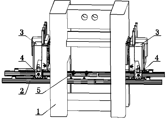
[0035] The up and down, inside and outside, front and back, and left and right mentioned in the present invention all use figure 1 The orientation in is the reference.

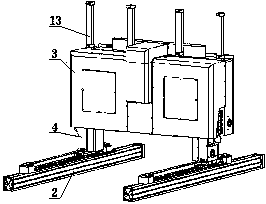
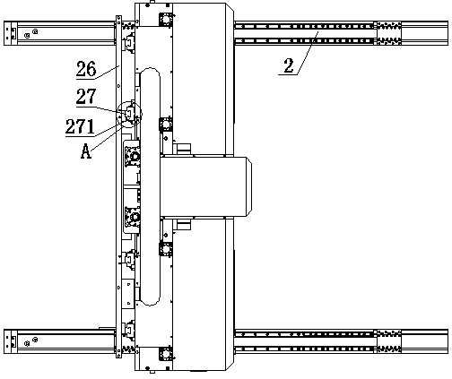
[0036] Such as Figure 1~11 As shown, a three-dimensional manipulator transfer device for stamping equipment includes a clamp arm 2 and a transmission body 3, the transmission body 3 includes a frame 6, and the frame 6 is provided with a support arm 4 that can drive the support arm 4 up and down The moving lifting transmission mechanism and the clamping transmission mechanism that can drive the support arm 4 to move inside and outside, the support arm 4 is slidably connected with the clamp arm 2, and the clamp arm 2 is equipped with a clamp 5 that can clamp the stamping parts. 4. There is a left and right traverse transmission mechanism that can drive the clamp arm 2 to move left and right. The number of the support arm 4 and the clamp arm 2 is two, and the support arm 4 and the clamp arm 2 are symmetrically ...


PUM


Abstract

The invention relates to the technical field of stamping automation, in particular to a three-dimensional mechanical arm conveyer for stamping equipment. The three-dimensional mechanical arm conveyer for the stamping equipment comprises two fixture arms and a transmission body, and the transmission body comprises a rack which is provided with two supporting arms, a lifting transmission mechanism and a clamp opening transmission mechanism. The lifting transmission mechanism can drive the supporting arms to move up and down, the clamp opening mechanism can drive the supporting arms to move inwards and outwards, the two supporting arms are connected with the two fixture arms in a sliding mode, fixtures which can clamp stamping parts are mounted on the fixture arms, the supporting arms are provided with left-right transversely moving transmission mechanisms which can drive the fixture arms to move from left to right, the two supporting arms are symmetrically arranged on the front side of the rack, and the two fixture arms are symmetrically arranged on the back side of the rack. By means of the three-dimensional mechanical arm conveyer for the stamping equipment, lifting and transmission strength can be uniform, the occupied space of the transversely moving conveying part is reduced, and the three-dimensional mechanical arm conveyer can cooperate with large stamping equipment in use.

Description

technical field [0001] The invention relates to the technical field of stamping automation, in particular to a three-dimensional manipulator transfer device used in conjunction with stamping equipment. Background technique [0002] Stamping die is a process equipment for processing materials (metal or non-metal) into parts (or semi-finished products) in cold stamping processing, called cold stamping die (commonly known as cold stamping die). Stamping is a pressure processing method that uses a mold installed on a press to apply pressure to the material at room temperature to cause separation or plastic deformation to obtain the required stamping parts. [0003] There are many forms of stamping dies. According to the degree of process combination, stamping dies include progressive dies (also called continuous dies) and single-process dies. The progressive dies have two or more stations in the feeding direction of the blank. In one stroke of the press, two or more stamping p...

Claims


Application Information

Patent Timeline
Patent Type & Authority Applications(China)
IPC IPC(8): B21D43/10B25J9/02B25J9/10
Inventor 张宇波
Owner DONGGUAN JINGTIAN AUTOMATION EQUIP
Why Eureka
Try Eureka