

Extended depth of field using a multi-focal length lens with a controlled range of spherical aberration and a centrally obscured aperture
a multi-focal length, centrally obscured technology, applied in the field of images, can solve the problems of large amount of light loss, difficult processing, and difficult to photograph objects clearly that span a large range of such distances, and achieve the effects of reducing image contrast, reducing side lobe oscillation, and increasing contras
Active Publication Date: 2006-03-09
SEMICON COMPONENTS IND LLC
View PDF35 Cites 91 Cited by
- Summary
- Abstract
- Description
- Claims
- Application Information
AI Technical Summary
Benefits of technology
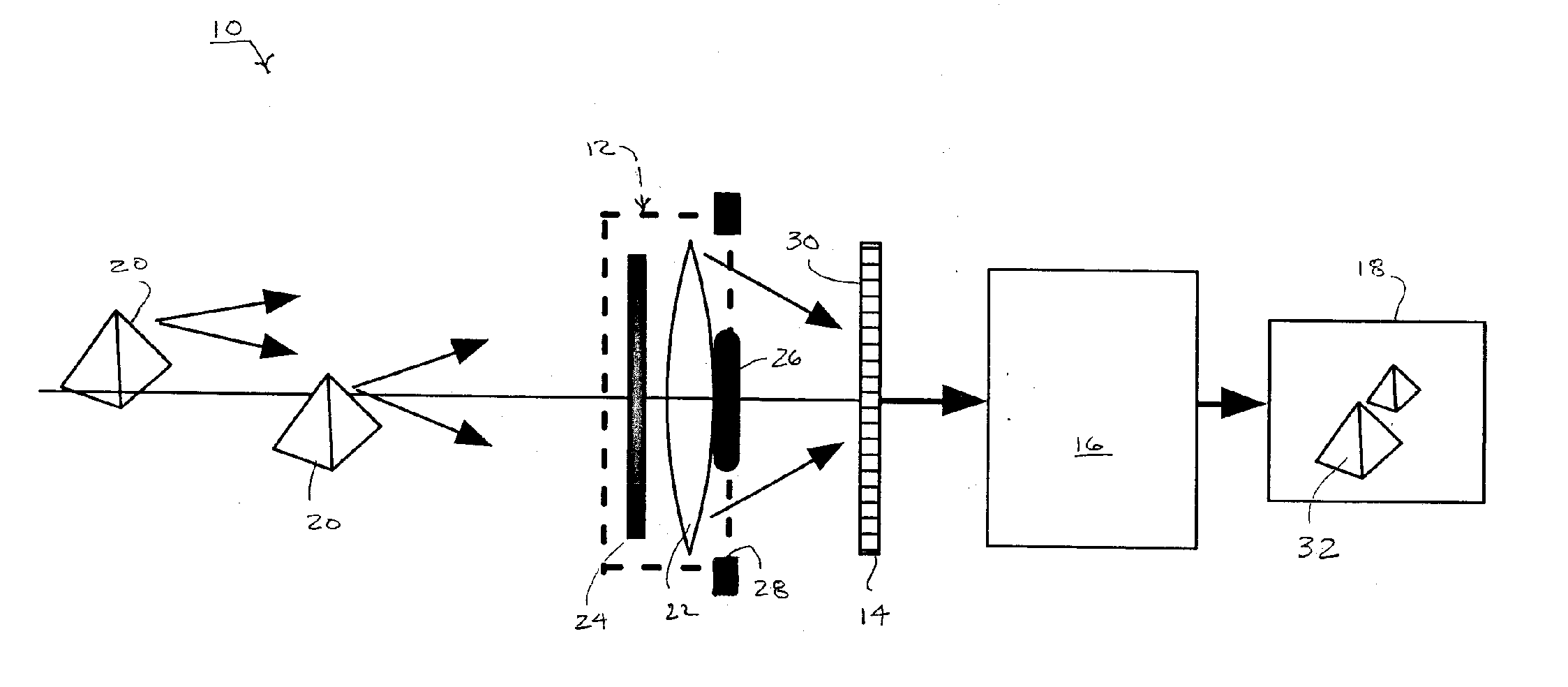
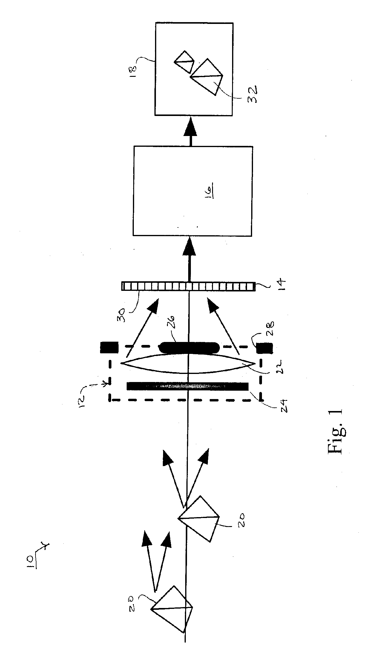
[0010] Our invention, in one or more preferred embodiments, incorporates a multifocal imaging subsystem that purposefully blurs intermediate images of objects such as by introducing a controlled amount of spherical aberration to provide a more uniform impulse response over a range of focal depths. Third order spherical aberration is preferably the dominant feature of the purposeful blur. A digital processing subsystem recovers images convoluted through the more uniform impulse response for producing likenesses of the objects that remain in focus through an extended range of object depths. The multifocal imaging subsystem that purposefully blurs intermediate images is preferably circularly symmetric with a centrally obscured aperture, which narrows the impulse responses and avoids conditions such as contrast inversion for larger amounts of defocus. Together, the controlled spherical aberration and the centrally obscured aperture provide a sufficiently narrow and invariant impulse response over the extended depth of focus for achieving diffraction-limited performance over the extended range far exceeding classical limits. Diffraction-limited performance over a depth of field increased by six to ten times the classical limit can be achieved. The circularly symmetric structure of the imaging subsystem simplifies manufacture and reduces overall costs.
Problems solved by technology
Even with these means, it is difficult to photograph objects clearly that span a large range of such distances.
The multiple images take time to collect, are difficult to process, and are generally unsatisfactory for scenes subject to change.
However, the filter introduces large amount of light loss, which limits its applications.
Although significant improvement in the depth of field is achieved, the cubic phase mask is not rotationally symmetric and has proven to be expensive and difficult to fabricate.
However, for the log-asphere lens, the impulse response is not perfectly uniform over the full range of operation, and as a result, some degradation is experienced in the image quality of the recovered image.
Reconstruction algorithms for removing the blur of such intermediate images are subject to problems relating to the quality and efficiency of their results.
Nonlinear processing algorithms can suffer from slow convergence or stagnation and produce images with reduced contrast at high spatial frequencies.
Method used
View moreImage
Smart ImageViewing Examples

Examples
case ii
) Assume λ3 is small relative to λ1 and λ2.
[0122] In this case, λ3≈0, y3=0 in Equation (31), and also: [z1z2z3=0]=[λ1000λ20000][y1y2y3=0](42)
[0123] Then, Equations (32) and (33) become: St=S0+ARTdiag(1λ1,1λ2,0)Z-12ZTZ(43)Ct=C0+MRTdiag(1λ1,1λ2,0)Z+12ZTPZ,(44)
where: P=diag(1λ1,1λ2,0)RNRTdiag(1λ1,1λ2,0)
[0124] A second rotation matrix V is introduced, such that VPVT=[μ1000μ2000μ3=0] where(45)V=[v11v120v21v220000]
A new variable U is defined as:
Login to View More PUM
 Abstract
An extended depth of field is achieved by a computational imaging system that combines a multifocal imaging subsystem for producing a purposefully blurred intermediate image with a digital processing subsystem for producing a recovered image having an extended depth of field. The multifocal imaging system preferably exhibits spherical aberration as the dominant feature of the purposeful blur. A central obscuration of the multifocal imaging subsystem renders point-spread functions of object points more uniform over a range of object distances. An iterative digital deconvolution algorithm for converting the intermediate image into the recovered image contains a metric parameter that speeds convergence, avoids stagnations, and enhances image quality.
Description
RELATED APPLICATIONS [0001] This application claims priority to U.S. Provisional Application No. 60 / 522,990 filed Nov. 30, 2004 and to U.S. Provisional Application No. 60 / 607,076 filed Sep. 3, 2004. Both provisional applications are hereby incorporated by reference.TECHNICAL FIELD [0002] The invention relates to imaging scenes or other objects that can be brought to focus by combining a blurred intermediate image with digital processing that produces a recovered image having an extended depth of field. Particular applicability is found for the invention in photographic applications, although other applications including pattern recognition, detection, microscopy, machine vision, and optical measurement can also benefit from the invention. BACKGROUND OF THE INVENTION [0003] Objects imaged by conventional imaging subsystems are sharply in focus over a limited distance known as the depth of field, which is inversely proportional to the square of the imaging system's numerical aperture ...
Claims
Login to View More Application Information
Patent Timeline
 Patent Type & AuthorityApplications(United States)
IPC IPC(8): G02B13/18
CPCG02B27/0075H04N5/23229G06T5/50H04N23/958G02B13/18H04N23/80
InventorGEORGE, NICHOLASCHI, WANLI
OwnerSEMICON COMPONENTS IND LLC