
Apparatus and method for laser treatment with spectroscopic feedback

a laser treatment and spectroscopic feedback technology, applied in the field of laser treatment apparatus and method, can solve the problems of hypertrophic scarring, poor reproducibility, and large variation

Inactive Publication Date: 2007-05-15
THE GENERAL HOSPITAL CORP +1
View PDF36 Cites 203 Cited by
  • Summary
  • Abstract
  • Description
  • Claims
  • Application Information

AI Technical Summary

Benefits of technology

[0074]It is another object of the invention to provide a laser treatment apparatus that can be easily modified and / or programmed to perform such different types of procedures.
[0080]The computer vision and control system may further be programmed to suppress image noise (e.g. through software filtering), improve contrast (through image processing), and subtract background details (e.g. through subtracting different images), thus, allowing target features to be enhanced in the image, which is impossible with the human visual system.
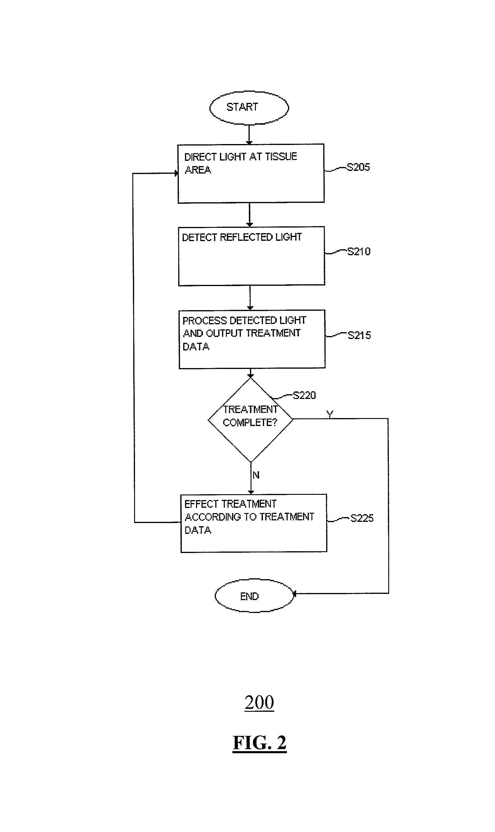
[0085]Even though selective photothermolysis is not critical to the Smart Scalpel system for effective treatment, the computer (software) control allows the laser energy of the treatment system to be modulated during treatment to further improve its effectiveness. The computer vision and control system can control the amount of laser energy, and the on / off state of the treatment system in real-time during treatment. There are many ways to do this modulation. For example, if a laser diode is used in the treatment system, it can be electronically modulated via the laser driver. Other instruments, such as opto-electro modulators, opto-acoustic modulators, and mechanical shutters, may also be used for such modulations. Thus, the combination of imaging, computer vision, and laser treatment control allows the laser parameters to be adjusted in real-time to accommodate variations in tissue properties (spatial and temporal). For example, when the computer “sees” a larger target during treatment, it may instruct the laser to dwell at that target for a longer time, and also to shift its focusing lenses to create a larger spot size. As a result, targets on a treatment site may be treated differently depending on their respective characteristics.
[0087]The real-time, rapid feedback control of the Smart Scalpel system also compensates for patient movements during the treatment. In accordance with an embodiment of the invention, the imaging, analysis, and treatment are performed at a rate such that they adjust for any bodily motion. The Smart Scalpel system may further include analysis and control processes that can reliably predict bodily movements, and anticipate target positions temporally.
[0089]In accordance with an exemplary embodiment of the present invention, the Smart Scalpel system may be used to target and treat nevus flammus (port wine stain or “PWS”) and other hemangiomas. It may utilize lights of 577 nm and 650 nm to illuminate skin tissue from the same position, polarizers at the light output, and an imaging camera. Accordingly, a combination of Orthogonal Polarization Spectroscopy (“OPS”) and Optical Reflectance Spectroscopy (“ORS”) may be used for non-invasively identifying blood vessels from other tissues. The ORS-OPS technique may also be used to discriminate normal vessels, untreated PWS vessels, and treated vessels from one another based on their respective reflectance characteristics, thus monitoring tissue changes throughout a treatment to optimally photocoagulate the blood vessels.

Problems solved by technology

Most of the laser treatment methods used today share a common disadvantage: all require great expertise with poor reproducibility, and this creates a great variation in the results.
There are reported problems such as hypertrophic scarring and inhomogeneity of blanching due to inhomogeneous energy delivery and dosage.
In addition, these manual methods are tedious and time-consuming, and usually require several sessions over a period of months.
Furthermore, many conventional methods require manually moving a handpiece over a treatment area, and as a result, this movement is operator dependent and duplication of initial treatment motion is not possible with subsequent applications.
The speed of the handpiece moving across the lesion is also not controlled.
Therefore, each of these inconsistencies may result in very inaccurate coverage due to poor dosimetry.
None of these patents, however, discloses or suggests a laser treatment apparatus with a flexible control platform that provides for accurate, real-time, and non-invasive targeting and treatment for different types of procedures.

Method used


Image

  • Apparatus and method for laser treatment with spectroscopic feedback
  • Apparatus and method for laser treatment with spectroscopic feedback
  • Apparatus and method for laser treatment with spectroscopic feedback

Examples


Embodiment Construction

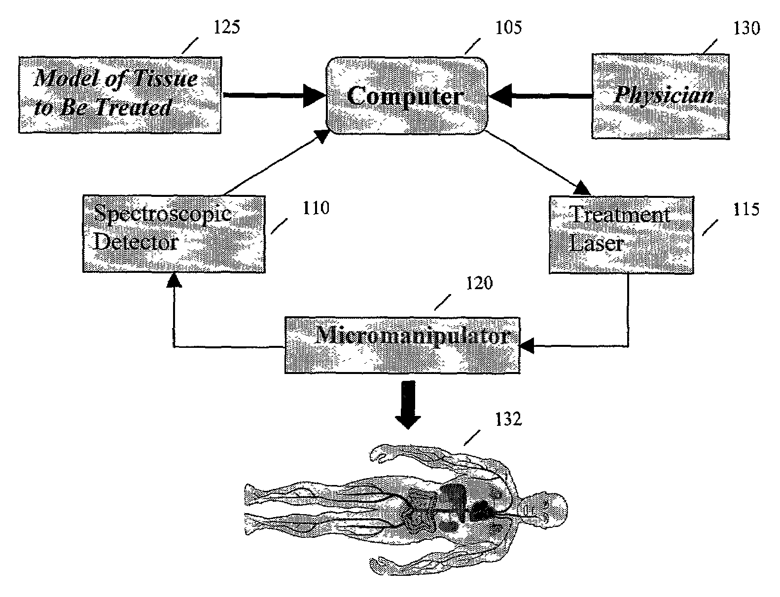
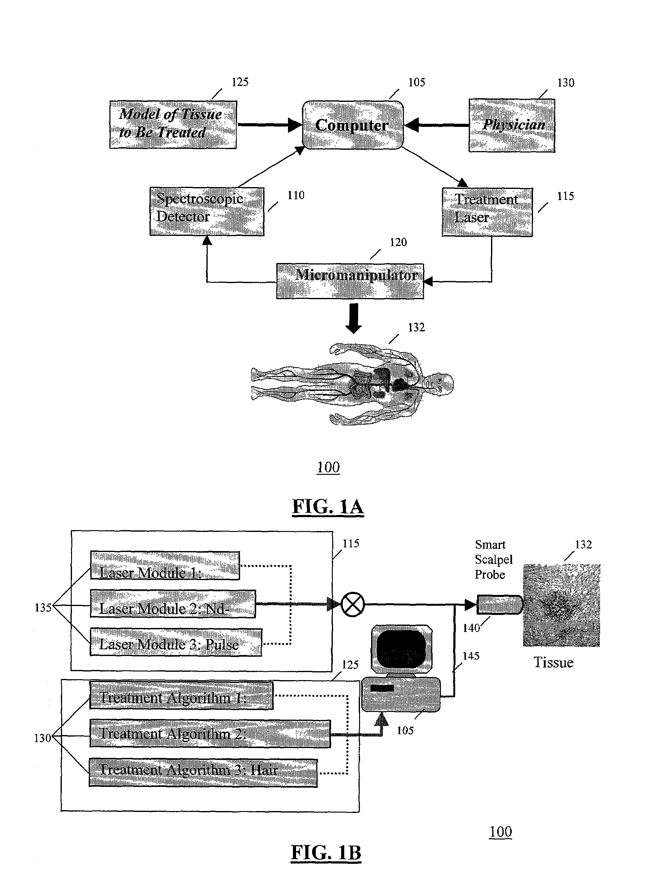
[0125]FIGS. 1A and 1B illustrate a Smart Scalpel system 100 in accordance with an embodiment of the present invention. As shown in FIG. 1A, Smart Scalpel system 100 includes a computer 105, a spectroscopic detector 110, a treatment laser 115, and a micromanipulator 120. Tissue model (physical properties) 125, as well as expert knowledge from a physician 130, describing a number of tissue attributes (e.g., those of healthy tissues versus those of diseased tissues to be excised) and / or targeting / treatment parameters may be input to computer 105. Computer 105, based on the inputted properties and / or parameters, may control spectroscopic detector 110 and treatment laser 115, which may be included in micromanipulator 120. Micromanipulator 120, which may be a handheld device, an automated apparatus, or the like, serves as an interface between a tissue volume (patient) 132 and Smart Scalpel 100, providing a convenient way to extract information about tissue state and to direct therapeutic ...


PUM


Abstract

A platform Smart Scalpel system using rapid real-time feedback for effecting laser treatment. The platform system includes an imaging system for rapid real-time detection of tissue characteristics, a processing system for processing the detected characteristics, and a treatment system for effecting treatment in accordance with results of the processing. The platform system provides for preprogramming and real-time inputting conditions and parameters for diagnosis using the imaging system and / or treatment using the treatment system.

Description

FIELD OF THE INVENTION[0001]The present invention relates to a laser treatment apparatus and method that utilizes continuous feedback control for locating and identifying treatment targets and for delivering appropriate treatment to the treatment targets.[0002]Each of the applications and patents cited in this text, as well as each document or reference cited in each of the applications and patents (including during the prosecution of each issued patent; “application cited documents”), and each of the PCT and foreign applications or patents corresponding to and / or claiming priority from any of these applications and patents, and each of the documents cited or referenced in each of the application cited documents, are hereby expressly incorporated herein by reference. More generally, documents or references are cited in this text, either in a Reference List before the claims, or in the text itself; and, each of these documents or references (“herein-cited references”), as well as eac...

Claims


Application Information

Patent Timeline
Patent Type & Authority Patents(United States)
IPC IPC(8): A61B18/18A61B18/20A61B17/00A61B19/00
CPCA61B5/0059A61B5/448A61B5/4836A61B5/489A61B5/72A61B18/20A61B5/0095A61B2019/2249A61B18/203A61B19/5225A61B2017/00061A61B2018/00452A61B2018/00458A61B2018/00476A61B2018/00636A61B2018/00904A61B2019/223A61B2019/2242A61B34/35A61B34/71A61B34/72A61B90/37A61B5/0036
Inventor ANDERSON, R. ROXHUNTER, IAN W.BRENAN, COLIN J. H.LIM, KENG HUISEBERN, ELIZABETH
Owner THE GENERAL HOSPITAL CORP
Learn More