Heat pipe having wick structure

a technology of wick and heat pipe, which is applied in the direction of electrical equipment, lighting and heating equipment, and semiconductor devices, etc., can solve the problems of relatively high thermal resistance and low heat transfer capacity of wick, and achieve high heat transfer and evaporator surface area, low thermal resistance, and high capillary force

Inactive Publication Date: 2006-01-26
HON HAI PRECISION IND CO LTD
View PDF10 Cites 26 Cited by
  • Summary
  • Abstract
  • Description
  • Claims
  • Application Information

AI Technical Summary

Benefits of technology

[0013] According to the heat pipe of the present invention, due to the plurality of first through holes defined in the wick in the evaporator section of the heat pipe, the wick comprises larger evaporator surface area. Thus, the containing amount of the working fluid at the evaporator section becomes larger. On the other hand, the wick is made by sintering the nano-scale metal powders and has nano-scale void spaces. Therefore, the preferred embodiment of the present invention provides a heat pipe with performances of low thermal resistance, high heat transfer and evaporator surface area, high capillary force and heat transfer capacity.

Problems solved by technology

However, because of the large particle size of the powder and small evaporator surface area of the sintered wick, the wick has relatively high thermal resistance and low heat transfer capacity.

Method used


Image

  • Heat pipe having wick structure
  • Heat pipe having wick structure
  • Heat pipe having wick structure

Examples


Embodiment Construction

[0019] Reference will now be made to the drawings to describe the preferred embodiments in detail.

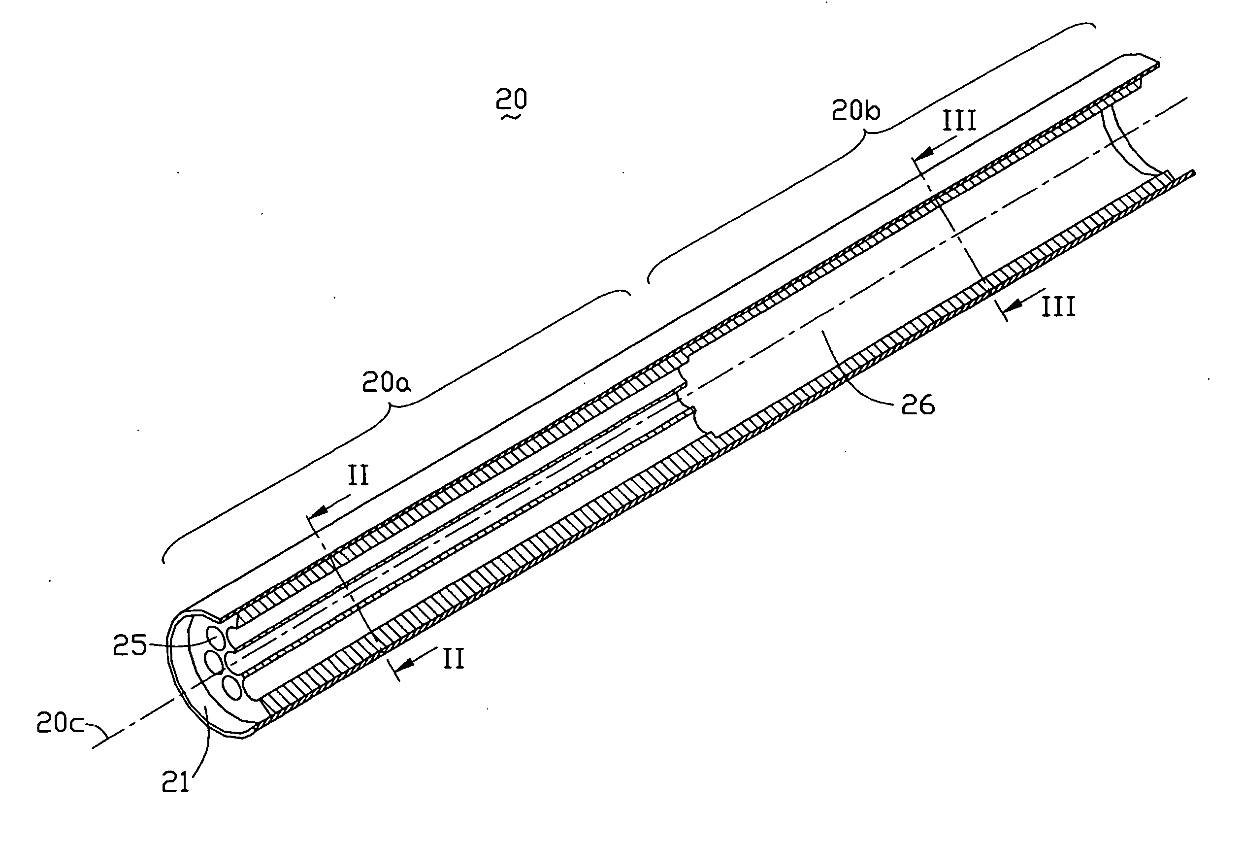
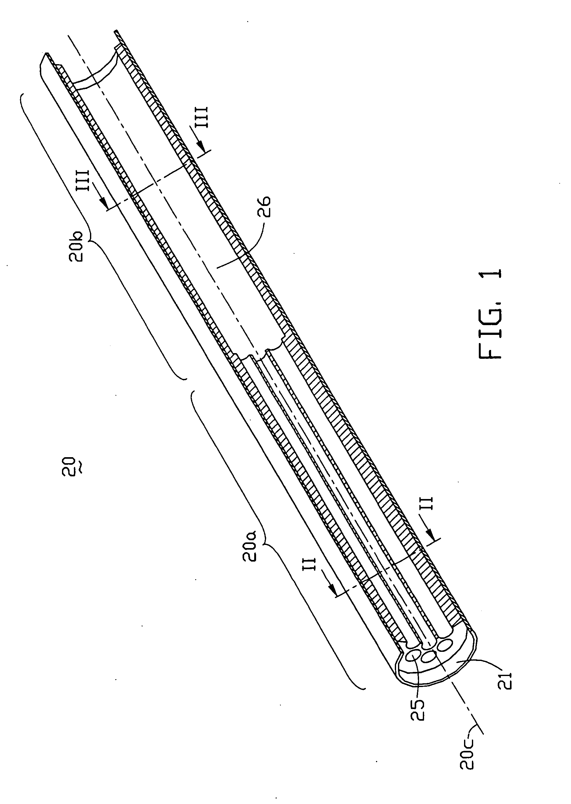
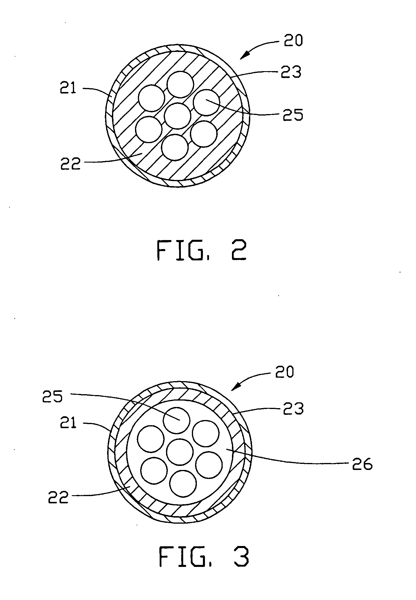
[0020] Referring to FIGS. 1, 2 and 3, a heat pipe 20 of a preferred embodiment includes a pipe 21, a structure of a wick 22 formed on an inner wall 23 of the pipe 21, and a working fluid (not shown) sealed in the pipe 21 and soaked in the wick 22. The heat pipe 20 further includes an evaporator section 20a in the thermal contact with an outer heat source to vaporize the working fluid from an originally liquid state thereof and a condenser section 20b in the thermal contact with a heat dissipation device like a heat sink to condense the vaporized working fluid back to the liquid state thereof. A plurality of first through holes 25 are defined in the wick 22 in the evaporator section 20a of the heat pipe 20. A central one of the first through holes 25 is aligned along an axis 20c of the heat pipe 20, and the other first through holes 25 are parallel to the axis 20c. A second through hole...


PUM


Abstract

A heat pipe (20) includes a pipe (21), a wick (22) formed on an inner wall (23) of the pipe, and a working fluid (not shown) sealed in the pipe and soaked in the wick. The wick is formed by sintering nano-size metal powder disposed inside the pipe. First through holes (25) are defined in the wick in an evaporator section (20a) of the heat pipe. A central one of the first through holes is aligned along an axis 20c of the heat pipe, and other first through holes are parallel to the axis 20c. A second through hole (26) is defined in the wick in a condenser section (20b) of the heat pipe. The second through hole communicates with the first through holes, whereby the working fluid flows through the first and second through holes. These characteristics give the wick low thermal resistance, a high evaporator surface area, and high capillary force.

Description

BACKGROUND OF THE INVENTION [0001] 1. Technical Field [0002] The present invention relates generally to heat transfer devices, and more specifically to heat pipes having wick structures. [0003] 2. Related Art [0004] A typical heat pipe transports heat in the form of latent heat of a working fluid thereof. The heat pipe is made of a heat conducting material. In assembly, air is evacuated from the heat pipe, a condensable fluid such as water is filled in the heat pipe, and then the heat pipe is sealed. The heat pipe is essentially a receptacle (container) which transports heat as latent heat of the working fluid therein. Heat input from outside the heat pipe evaporates the working fluid, the vapor flows to a condenser section of the heat pipe having a low temperature and a low pressure, the vapor condenses, and the released heat radiates from the condenser section of the heat pipe. Because the heat is transmitted in the form of latent heat of the working fluid, the heat pipe has from ...

Claims


Application Information

Patent Timeline
Patent Type & Authority Applications(United States)
IPC IPC(8): F28D15/00
CPCF28D15/046F28F2255/18H01L2924/0002H01L2924/00
Inventor LEE, HSIN-HOLIAO, WEI-JIAN
Owner HON HAI PRECISION IND CO LTD
Why Eureka
Try Eureka