

Image-forming device and scanning unit for use therein
- Summary
- Abstract
- Description
- Claims
- Application Information
AI Technical Summary
Benefits of technology
Problems solved by technology
Method used
Image

Examples
Embodiment Construction
[0025] A color laser printer according to an embodiment of the invention will be described with reference to the accompanying drawings. In the following description, the terms “upward”, “downward”, “upper”, “lower”, “above”, “below” and the like will be used throughout the description assuming that the color laser printer is disposed in an orientation in which it is intended to be used. In use, the printer is disposed as shown in FIG. 1.
(1) Overall Structure of a Color Laser Printer
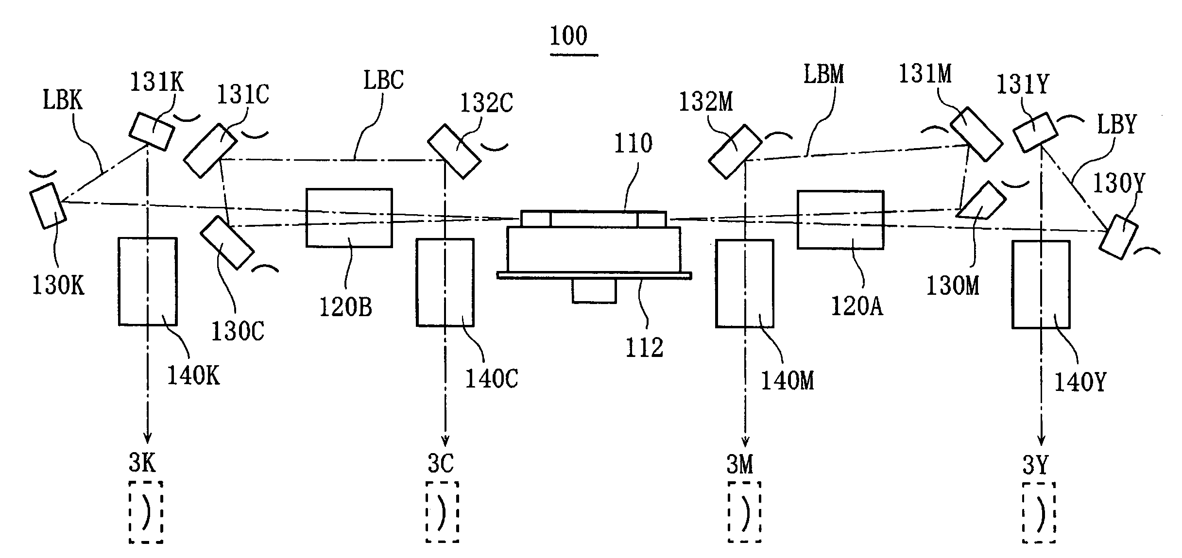
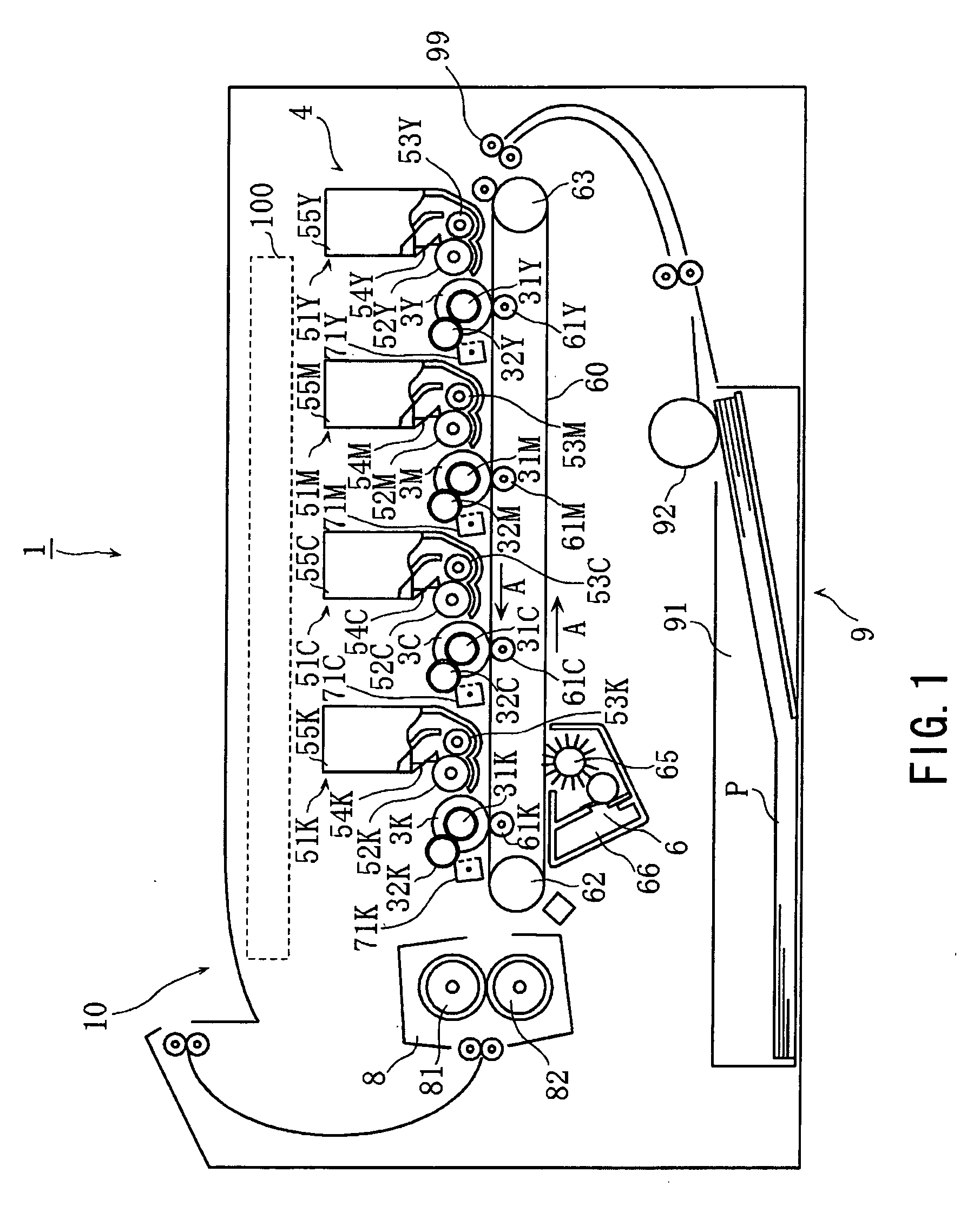
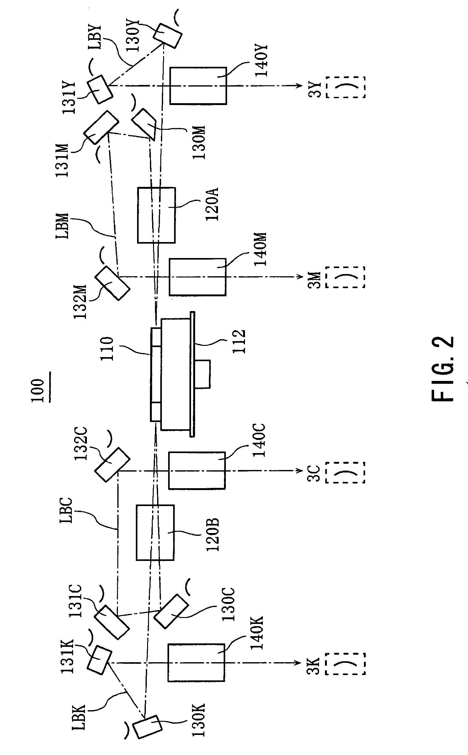
[0026]FIG. 1 is a side cross-sectional view showing the structure of a color laser printer serving as the color image-forming device according to the present invention.
[0027] A color laser printer 1 is a tandem type color image-forming device for forming color images on a recording medium, such as a recording paper P. The color laser printer 1 includes photosensitive drums 3Y, 3M, 3C, and 3K (hereinafter also referred to as the “photosensitive drums 3”) corresponding to the colors yellow (Y), magenta ...
PUM
 Abstract
Description
Claims
Application Information