Phase error detecting circuit and synchronization clock extraction circuit

a phase error detection and synchronization clock technology, applied in the field of phase error detection circuits, can solve problems such as narrow capture ranges, and achieve the effects of enhancing jitter, enhancing jitter, and expanding capture rang

Inactive Publication Date: 2006-03-02
SOCIONEXT INC
View PDF6 Cites 11 Cited by
  • Summary
  • Abstract
  • Description
  • Claims
  • Application Information

AI Technical Summary

Benefits of technology

[0012] An object of the present invention is to solve the problem mentioned above and thereby precisely detect the zero cross point even in the case where the reproduced data and the sampling clock are out of synchronization.
[0050] Thus, the present invention performs a feedback operation by using the phase error data detected in the preceding process, updates the reference value, and uses reproduced data at a timing at which the reference value crosses a reproduced signal as the next cross detection signal to detect the phase error data of the cross detection signal. Consequently, even in a situation in which the reproduced data and the sampling clock are out of synchronization, the phase error can be detected precisely and the capture range can be enlarged.
[0051] In particular, the present invention allows a shift to the zero cross method which generates the cross timing of the reproduced signal and the zero value as a cross detection signal after the phase error becomes smaller and approaching a steady state. As a result, the detection of the phase error can be performed efficiently and stably.
[0052] In addition, in the case where the phase error data detected in the preceding process is used as the reference value, when the reference value is larger than a set threshold, the present invention has limited the reference value to the set threshold and constrained the adopted reference value to a proper range. This suppresses the enhancement of a jitter in the reproduced signal and allows more precise detection of the phase error.

Problems solved by technology

Thus, the conventional phase error comparison method has the problem of a narrow capture range due to a narrow input linear range.

Method used


Image

  • Phase error detecting circuit and synchronization clock extraction circuit
  • Phase error detecting circuit and synchronization clock extraction circuit
  • Phase error detecting circuit and synchronization clock extraction circuit

Examples


embodiment 1

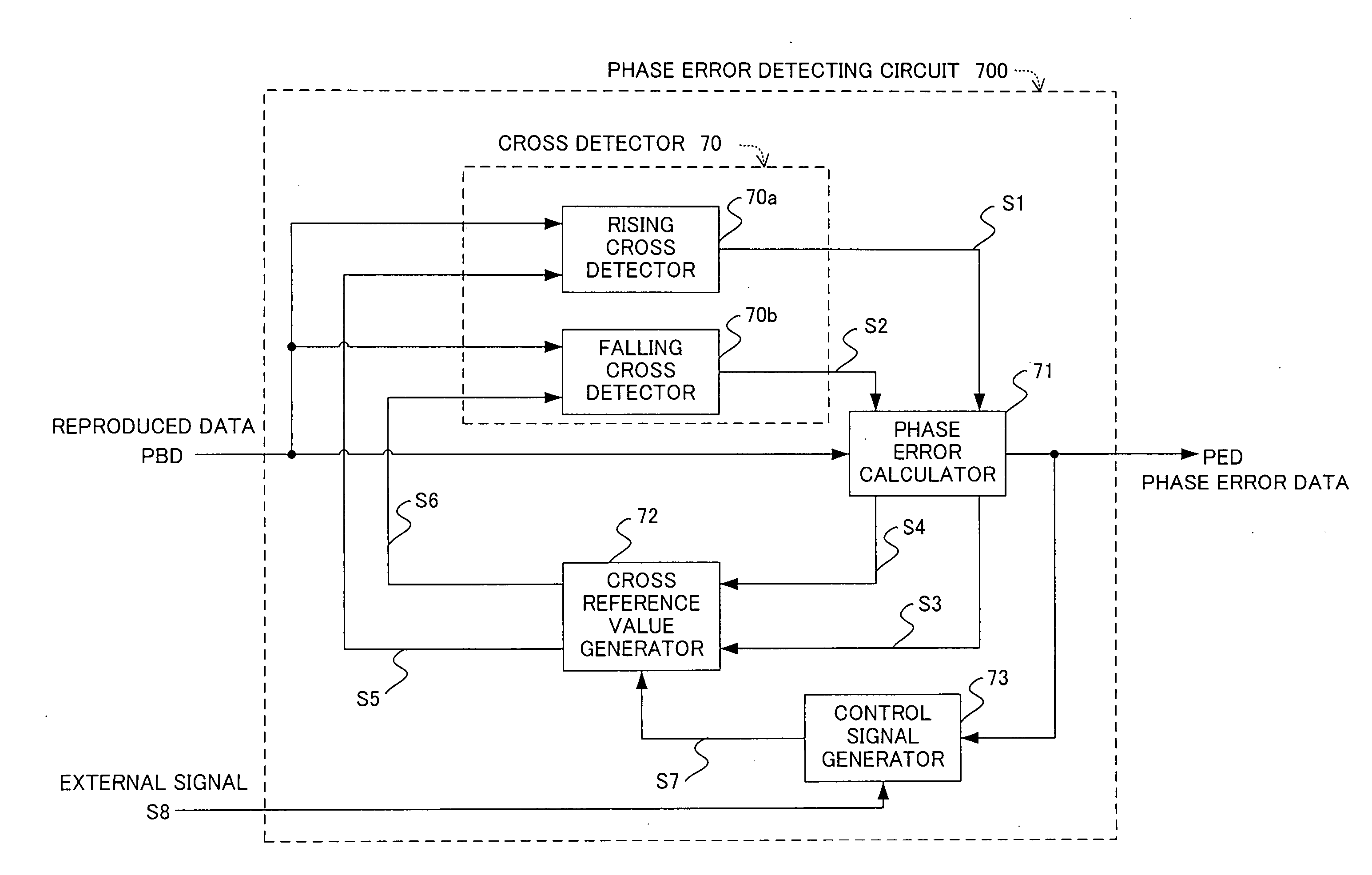
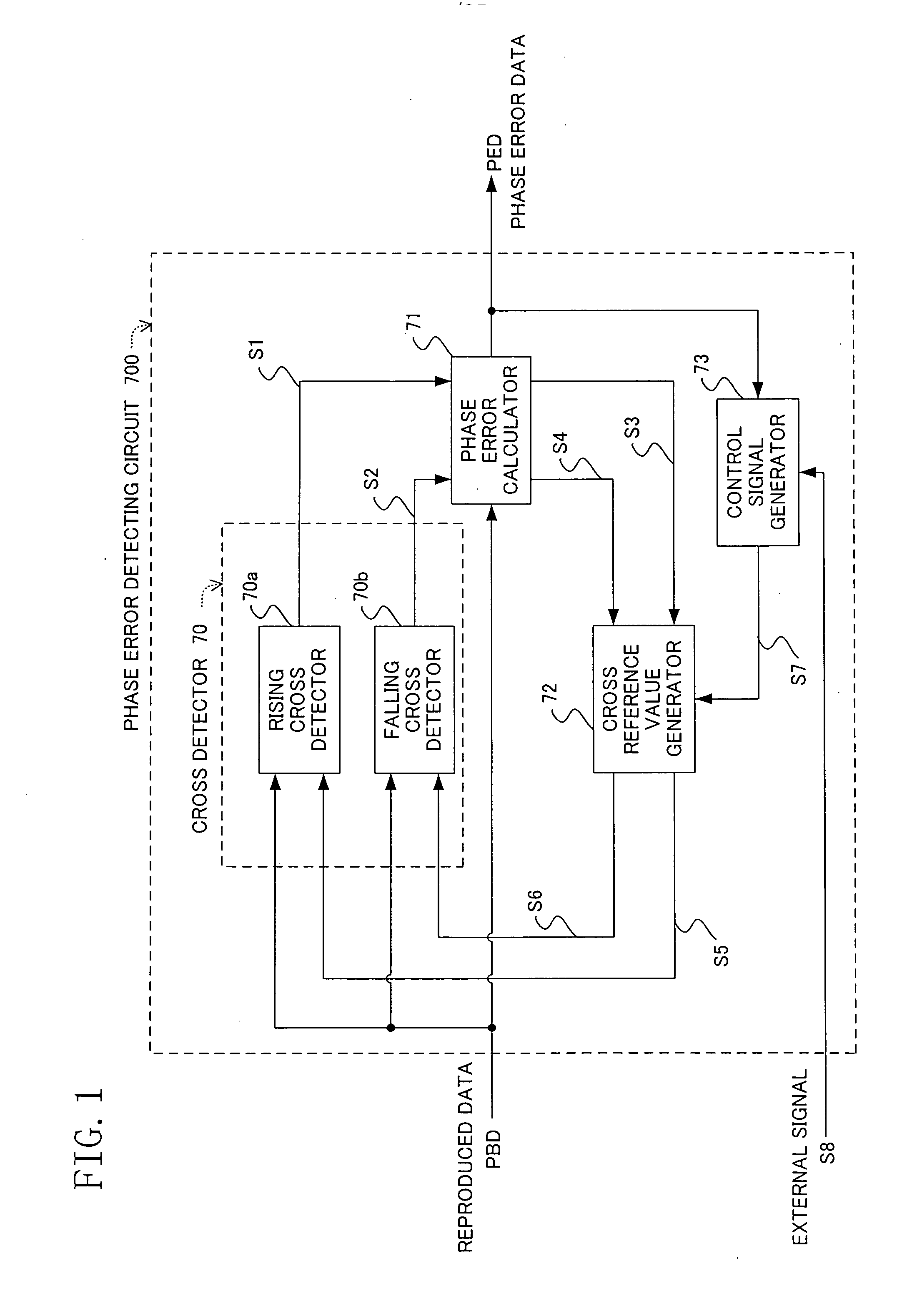
[0081]FIG. 1 shows a structure of a phase error detecting circuit as a first embodiment of the present invention. The phase error detecting circuit in the drawing is used as a replacement for the phase comparator 7 provided in the synchronous clock extracting circuit 13 of the digital signal processing circuit 12 in the reproduced signal processing circuit in the optical disk apparatus (record reproducing apparatus) shown in FIG. 12. Accordingly, the respective structures of the synchronous clock extracting circuit and the reproduced signal processing circuit each having the phase error detecting circuit are the same as in FIG. 12 so that the description thereof will be omitted.

[0082] In FIG. 1, 700 is the phase error detecting circuit which detects a phase error from the reproduced data reproduced by the record reproducing apparatus and subjected to AD conversion (quantization) in the A / D converter 4 shown in FIG. 23 and outputs the detected phase error. The phase error detecting ...

embodiment 2

[0097] A description will be given next to a phase error detecting circuit in the second embodiment. In the present embodiment, the cross reference value generator 72 generates a reference value different from that used in the first embodiment.

[0098] Specifically, the rising cross reference value S5 is outputted to the rising cross detector 70a and the rising cross reference value S5 having an equal absolute value and an inverted sign is outputted to the falling cross detector 70b, which will be described with reference to FIG. 6. The phase error data point PE3 upon the next rising is detected by using the level Lr at the phase error data point PE1 upon rising as the reference value and, for the detection of the phase error data points PE2 and PE4 upon falling, a value obtained by inverting the sign of the level Lr at the phase error data point PE1 upon rising is used as the reference value.

[0099] Accordingly, the capture range of the phase error detecting circuit can be enlarged ...

embodiment 3

[0100] A description will be given next to a phase error detecting circuit according to the third embodiment. In the present embodiment, another embodiment of the generation of the reference value will be shown.

[0101] Specifically, the falling cross reference value S6 is outputted to the falling cross detector 70b by using the falling phase error data S4 inputted to the cross reference value generator 72, while the falling cross reference value S6 having an equal absolute value and an inverted sign is outputted to the rising cross detector 70a, which will be described with reference to FIG. 7. By using the level Lf at the phase error data point PE2 detected upon falling as the reference value, the phase error data point PE4 is detected upon the next falling and, for the detection of the phase error data point PE3 upon rising, a value obtained by inverting the sign of the level Lf at the phase error data point PE2 upon falling is used as the reference value.

[0102] Accordingly, the ...


PUM

PropertyMeasurementUnit
phase erroraaaaaaaaaa
phase error calculatoraaaaaaaaaa
falling phase erroraaaaaaaaaa

Abstract

In a phase error detecting circuit used in a synchronous clock extracting circuit for extracting a clock which is synchronized with reproduced data, a cross reference value generator 72 inputs, as a rising cross reference value S5, rising phase error data S3 calculated in a phase error calculator 71 to a rising cross detector 70a and inputs, as a falling cross reference value S6, falling phase error data S4 similarly calculated to a falling cross detector 70b. Each of the cross detectors 70a and 70b calculates a difference value between the value of the reproduced data at a sampling point and the inputted cross reference value (cross offset value) S5 or S6 and outputs a rising or falling cross detection signal when one of two difference values at consecutive sampling points is negative and the other thereof is positive. Accordingly, a capture range is enlarged.

Description

TECHNICAL FIELD [0001] The present invention relates to a phase error detecting circuit used, in a reproduced signal processing circuit for extracting data recorded in a recording medium such as an optical disk or a magnetic disk therefrom and extracting a synchronous clock which is synchronized with the data extracted, to extract the synchronous clock. BACKGROUND ART [0002] An example of a reproduced signal processing circuit in a conventional optical disk apparatus is shown in FIG. 12. [0003] In FIG. 12, 1 is a recording medium such as an optical disk, 2 is an optical pick-up, 3 is an analog front end, and 12 is a digital signal processing circuit. In the digital signal processing circuit 12 mentioned above, 4 is an A / D converter, 5 is a digital filter, 6 is a decoder, and 13 is a synchronous clock extracting circuit. In the synchronous clock extracting circuit 13 mentioned above, 7 is a phase comparator, 8 and 11 are loop filters, 9 is a VCO (voltage control oscillator), and 10 i...

Claims


Application Information

Patent Timeline
Patent Type & Authority Applications(United States)
IPC IPC(8): G11B7/00G11B20/10G11B20/14G11B20/18H03L7/091H04L7/033
CPCG11B20/10009H04L7/0334H03L7/091G11B20/18
Inventor KAWABE, AKIRAOKAMOTO, KOUJI
Owner SOCIONEXT INC
Why Eureka
Try Eureka