Vacuum nozzle for spray system

a technology of vacuum nozzle and spray system, which is applied in the direction of spray nozzle, vacuum evaporation coating, coating, etc., can solve the problems achieve the effect of reducing the efficiency of vacuum, reducing the turbulent flow of air, and efficient air drawing

Inactive Publication Date: 2006-04-20
DOBEN LTD
View PDF5 Cites 20 Cited by
  • Summary
  • Abstract
  • Description
  • Claims
  • Application Information

AI Technical Summary

Benefits of technology

[0007] To provide more efficient collection of the undeposited material and gas in the work area, a shield at the end portion of the collection assembly is arranged to more efficiently draw air into the collection assembly. In one example, the shield includes a flange that extends radially outwardly from the collection assembly and is generally parallel to the substrate. An angled portion of the shield extends from the collection assembly. A radius portion adjoins the flange and the angled portion. The profile of the inner surface of the shield provides a smooth transition for air entering the collection assembly to minimize turbulent flow of the air into the collection assembly, which would reduce the efficiency of the vacuum.
[0008] The inventive collection assembly also includes a consumable ring at the end portion of the collection assembly. The ring is spaced between the spray nozzle and the shield. An inner surface of the ring deflects material that typically would otherwise not become adhered to the substrate back into the collection assembly to minimize the material that must be vacuumed at the substrate. A curved surface of the ring extends from a surface spaced from the substrate toward the shield to provide a smooth transition for materials flowing along the substrate back into the collection assembly. The curved surface of the ring minimizes turbulent flow from the substrate back into the collection assembly.
[0009] Accordingly, the present invention provides a cold spray system that is compact by providing efficient collection of the material and gases.

Problems solved by technology

The profile of the inner surface of the shield provides a smooth transition for air entering the collection assembly to minimize turbulent flow of the air into the collection assembly, which would reduce the efficiency of the vacuum.

Method used


Image

  • Vacuum nozzle for spray system
  • Vacuum nozzle for spray system
  • Vacuum nozzle for spray system

Examples


Embodiment Construction

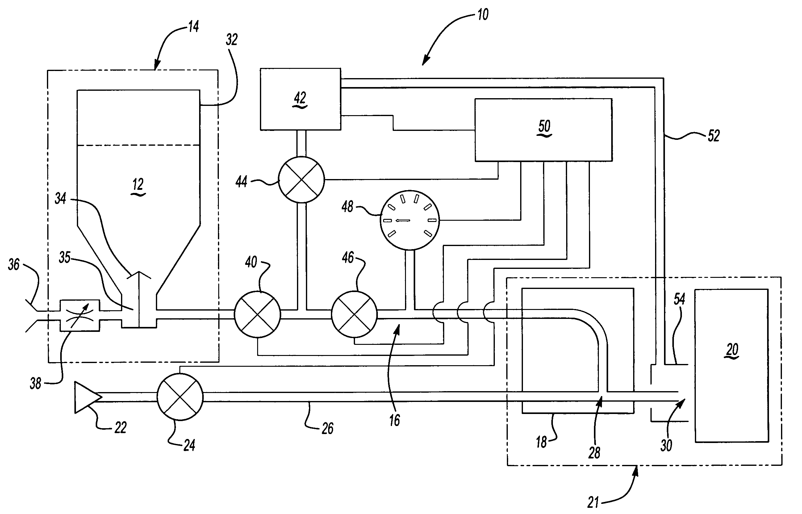
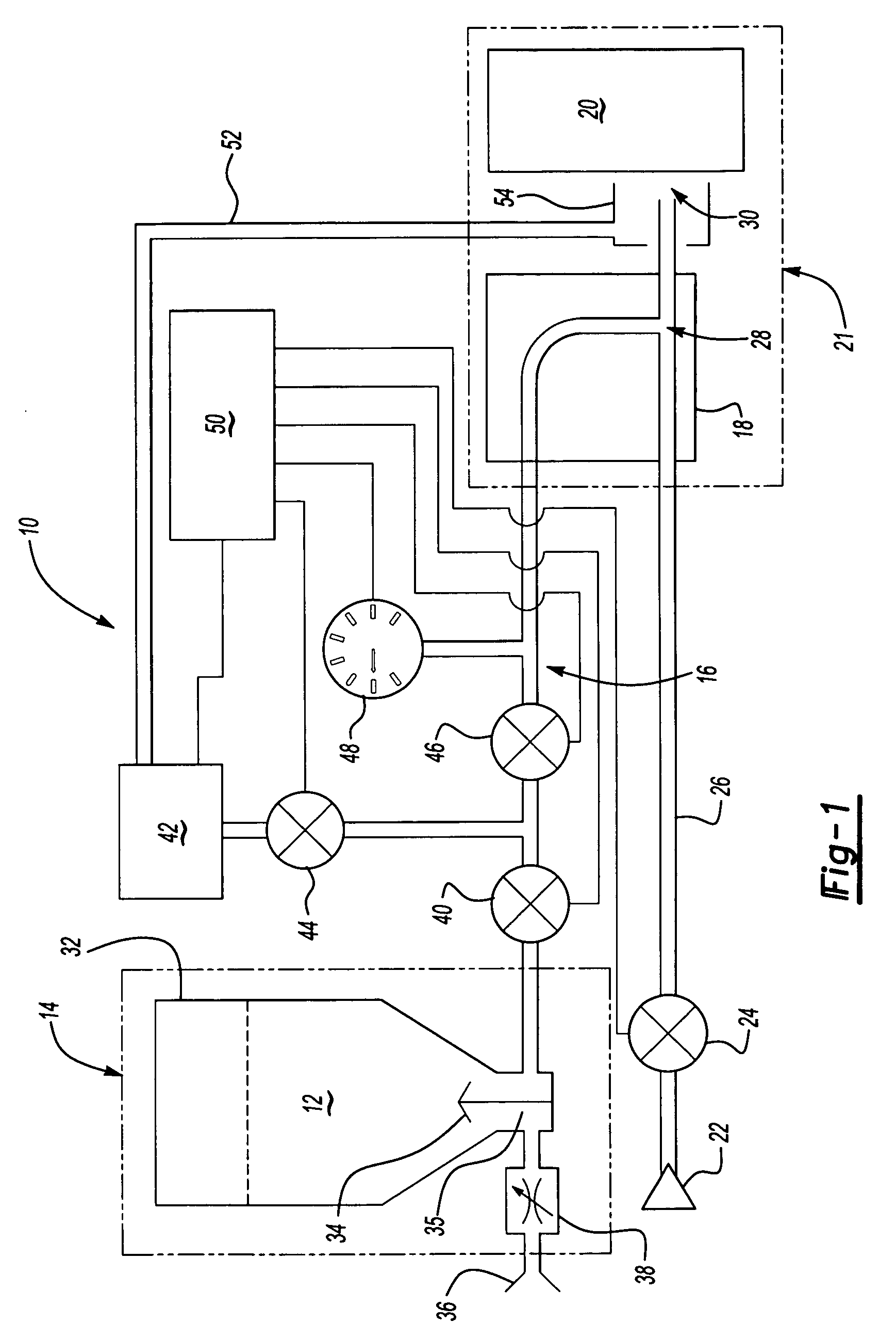
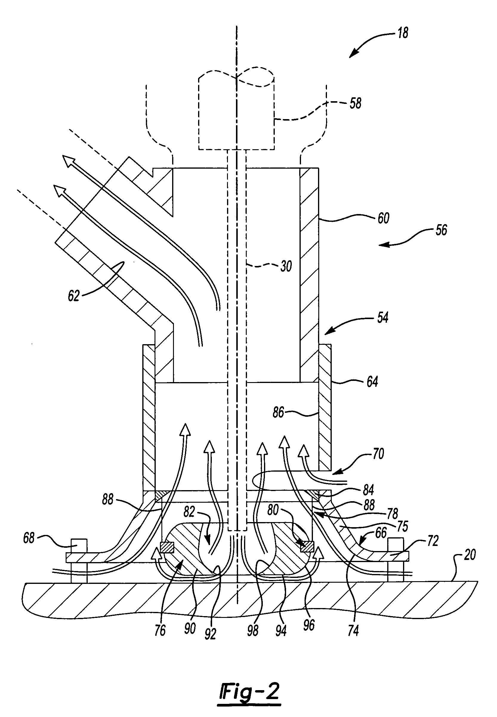
[0013] An example cold spray system 10 is schematically shown in FIG. 1. The system 10 deposits material 12 provided by a power feeder 14 through a feed line 16. The material 12 is directed onto a substrate 20 using a process applicator 18. The process applicator 18 includes a handheld unit 54 (shown in FIG. 2) used in a work area 21 to deposit materials at supersonic speeds onto a substrate 20, such as an automotive body panel.

[0014] A propulsion gas supply 22 provides a compressed gas, for example at a pressure of between 60 and 100 psi, to create supersonic velocities of the material exiting the process applicator 18. The compressed gas flows from the propulsion gas supply 22 through a gas valve 24 along a pressure line 26 to an intersection 28 in the process applicator 18. Material 12 flowing through the feed line 16 is introduced to the compressed gas at the intersection 28. The pressure line 26 pulls a vacuum on the feed line 16. A venturi (not shown) is arranged upstream of ...


PUM

PropertyMeasurementUnit
pressureaaaaaaaaaa
pressureaaaaaaaaaa
transparentaaaaaaaaaa

Abstract

A cold spray system includes a spray nozzle for depositing material onto a substrate. A collection assembly at least partially surrounds the spray nozzle for vacuuming undepositive material and gases in the work area. The collection assembly includes a transparent collection tube at an end portion of the collection assembly to provide visibility to the work area. The collection assembly includes a shield having a flange that extends radially outwardly from the collection assembly and is generally parallel to a substrate. An angled portion of the shield extends from the collection assembly. A radius portion adjoins the flange and the angled portion. A ring is spaced between the spray nozzle and the shield. An inner surface of the ring deflects material that typically would otherwise not become adhered to the substrate back into the collection assembly to minimize the material that must be vacuumed at the substrate. A curved surface of the ring extends from a surface spaced from the substrate toward the shield to provide a smooth transition for materials flowing along the substrate back into the collection assembly.

Description

[0001] The present application claims priority to U.S. Provisional Patent Application Ser. No. 60 / 619,086, filed Oct. 15, 2004.BACKGROUND OF THE INVENTION [0002] This invention relates to a vacuum nozzle for a cold spray system. [0003] Cold spray systems are used to adhere materials to a substrate by flowing the material through a nozzle at supersonic speeds. The material becomes deformed and adheres to the substrate upon impact. Specifically, the material is entrained in a carrier gas. The material laden carrier gas is drawn into a supersonic flow compressed gas and is accelerated as it travels through an expanding nozzle. [0004] A portion of the material does not adhere to the substrate. In the case of using the system to abrade the substrate, similar to a media blaster, none of the material adheres to the substrate. In both cases, it is desirable to collect loose material in addition to the carrier and compressed gases. To this end, a collection system is used to vacuum any loose...

Claims


Application Information

Patent Timeline
Patent Type & Authority Applications(United States)
IPC IPC(8): B05B15/12B05B15/04B05C5/00
CPCB05B15/0406B05B15/0412B05B15/0425B05B14/10B05B14/30
Inventor BARAN, ZYGMUNT
Owner DOBEN LTD
Why Eureka
Try Eureka