Surgical hand-piece with a bottom fluid tube convertible from irrigation to aspiration

a technology of fluid tube and handpiece, which is applied in the field of work tips for surgical handpieces, can solve the problems of high negative evacuation pressure (suction) in the eye that cannot be safely achieved, collapse with high suction, etc., and achieves the effect of improving the efficiency of ultrasonic vibration and being easy to inser

Active Publication Date: 2022-11-22
SURGICAL DESIGN
View PDF22 Cites 0 Cited by
  • Summary
  • Abstract
  • Description
  • Claims
  • Application Information

AI Technical Summary

Benefits of technology

[0016]In accordance with the invention a surgical hand piece is provided with a solid vibrating blade, knife or scalpel with a sharp cutting edge located in a sleeve with multiple fluid channels, while retaining a uniform cross section. Further, a cobra cone shape is incorporated into the distal end of the blade to improve it efficiency
[0021]In a still further embodiment, a bottom irrigation tube is loosely attached (so not to dampen vibration) to the underside of the vibrating blade so it can be axially slid along the blade to change its operation. The tube has a large opening in its top surface at the distal end to supply irrigation fluid during phacoemulsification. The irrigation fluid flows through the bottom tube to the site where the sharp edge of the blade is contacting cataract tissue. Channels and baffles at the large opening in the bottom tube direct irrigation fluid out of the large hole in a particular pattern. Directing the irrigation fluid from the tube and within the eye is important to minimize turbulent flow in the eye.
[0023]The principles of the invention have numerous advantages. For example, the invention allows for a work tip that is easier to insert into an incision in the eye, but still provides multiple fluid flow paths for use in phacoemulsification and cleanup procedures. It also provides a cone shape to improve the efficiency of the ultrasonic vibrations. By causing the cone shape to interact with a structure in a surrounding sleeve, the work tip function can be changed from phacoemulsification to cleanup without having to remove the work piece from the surgical site, such as the eye, and to replace it with an irrigation / aspiration (I / A) cleanup tool. Further, according to the present invention, cleanup can be commenced without the surgeon having to divert his attention from the eye of the patient.
[0024]In addition, the present invention takes into consideration the control and direction of irrigation fluid within the eye by means of various grooves and baffles at the working end of the irrigation tube. This results in a more efficient method of delivering irrigation fluid closer to the vibrating tip and evacuation tube, and assuring a fluid flow that efficiently causes tissue particles created during phacoemulsification to exit the eye through the aspiration tube.

Problems solved by technology

For example, a very high negative evacuation pressure (suction) in the eye can only be safely achieved when using a very rigid, small internal diameter tubing for aspiration.
If the tubing is not rigid it will collapse with the high suction.

Method used


Image

  • Surgical hand-piece with a bottom fluid tube convertible from irrigation to aspiration
  • Surgical hand-piece with a bottom fluid tube convertible from irrigation to aspiration
  • Surgical hand-piece with a bottom fluid tube convertible from irrigation to aspiration

Examples


first embodiment

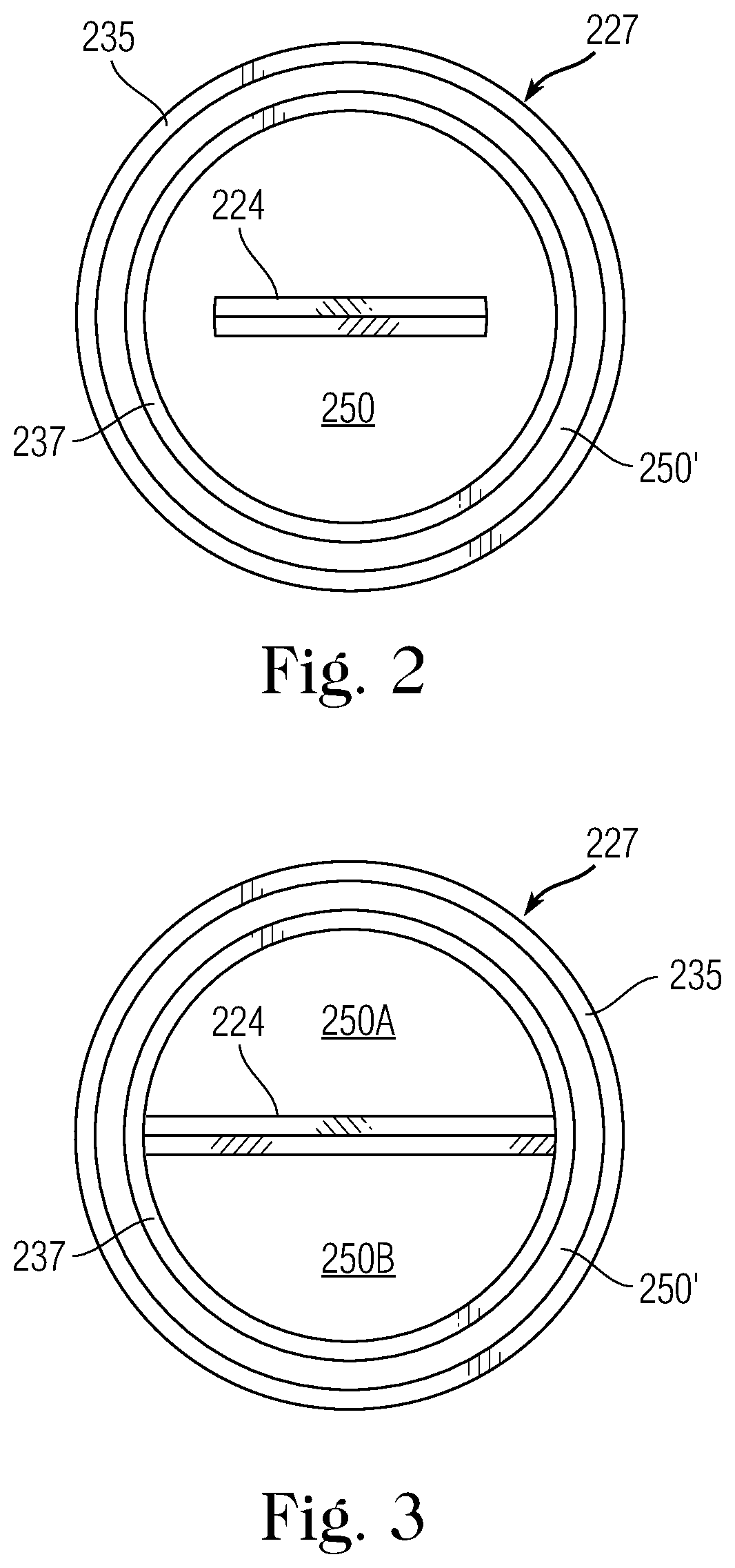
[0059]FIG. 2 shows an external sleeve 227 in the form of two concentric tubes 235, 237 for the present invention. The blade 224 is in the center of channel 250 but does not extend completely across the tube 237. With this arrangement irrigation fluid can flow in the channel 250′ between the tubes, while aspiration fluid can flow in channel 250 within tube 237.

[0060]In FIG. 3 the blade 224 extends completely across tube 237 and separates the channel 250 into two distinct chambers, 250A and 250B. Again, the irrigation is in channel 250′ between tubes 235, 237. However, because channel 250 has been divided into two channels, there are a total of three channels available that can be alternated or switched by the operation to change the performance. For example, the arrangement can have two aspiration channels and one irrigation channel, or one aspiration channel and two irrigation channels. It should be noted that in FIGS. 2 and 3 the sleeve 227 has a round shape which will make it easi...

second embodiment

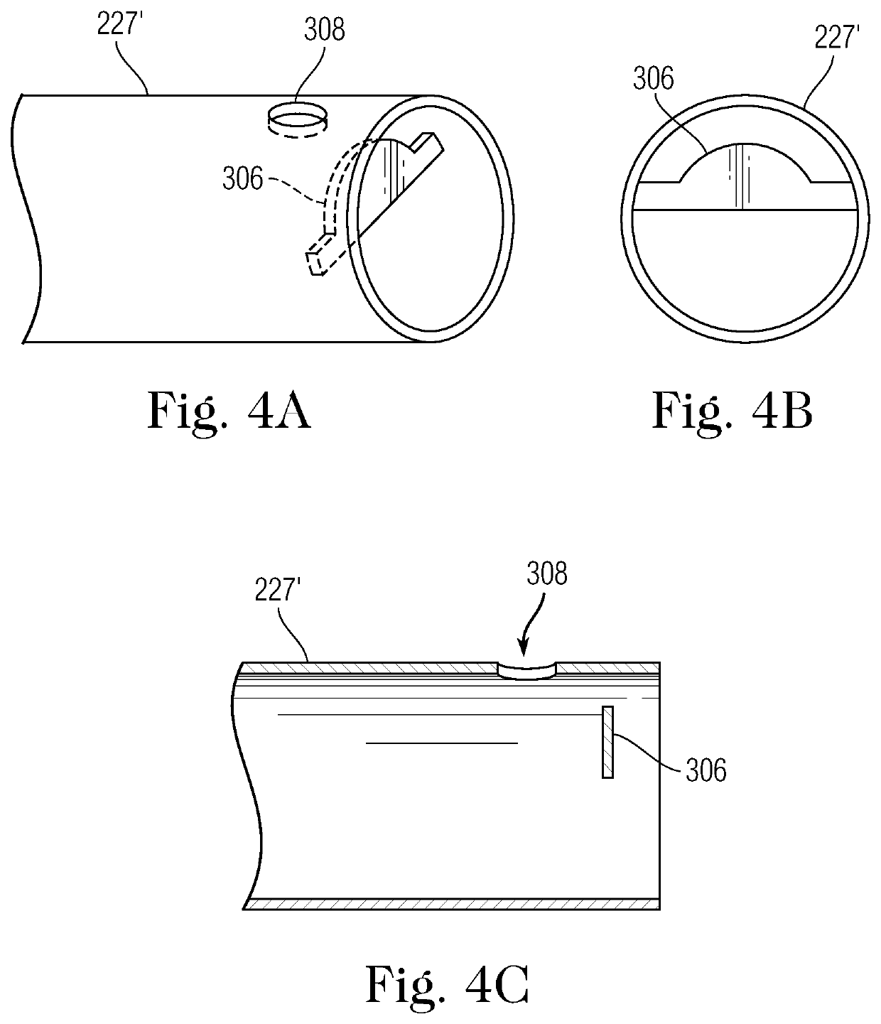
[0061]In FIG. 4A, which represents the invention, there is shown a small hole 308 in a single wall sleeve 227′. Because this sleeve has only a single wall, it cannot provide an outer irrigation channel. Instead, the single channel will need to be divided into irrigation and aspiration channels. As will be described in more detail below, the hole 308 can be used as the aspiration opening during cleanup. A structure 306 is shown suspended in the end of sleeve 227′ in the upper part. The shape of the structure is best seen in FIG. 4B. Also, the location of the structure with regard to the hole 308 can be determined in FIG. 4C.

third embodiment

[0062]The double wall sleeve 227 of FIGS. 2 and 3 or the single wall sleeve 227′ of FIGS. 4A-4C is designed to be used with one of the knives shown in FIGS. 5-10, as shown, for example in FIG. 11. FIG. 5, which is the invention, shows a connecting body or hub 222 with a knife 224 extending from it. At the distal end of the knife there is a half Cobra tip 300, i.e., a cylindrical body with a conical shape at its proximal end. FIG. 6 shows the connecting body or hub 222 and a rod 302 extending form it to a portion of a knife 224. The connecting body and the rod are fixed to each other by a threaded connection 312. The distal end of the knife has half Cobra tip 300 fastened to it. The rod and connecting body or hub may be formed as one piece to lower the cost of machining the part. As an alternative the rod and / or blade may screw into the connecting body.

[0063]The design of FIG. 7 is similar to that of FIG. 5, but without the connecting body or hub. The design of FIG. 8 is similar to t...


PUM


Abstract

A work tip for an ultrasonic surgical hand piece has a solid knife with a sharp distal edge. A first fluid tube located on one side of the knife and has open ends to receive or discharge fluid. A second fluid tube is located on the other side of the knife and is slidably connected with the knife. The second fluid tube has an opening at a distal end and a smaller side hole. During phacoemulsification the knife is vibrated independent of the fluid tubes. The second fluid tube has irrigation fluid passing from the opening and side hole, and the first fluid tube is positioned so as to receive fluid from the second tube. During I / A cleanup the second fluid tube receives aspiration fluid only through the side hole because the knife is positioned to block the aspiration fluid from entering through the opening.

Description

[0001]The present invention is a continuation-in-part of U.S. patent application Ser. No. 15 / 941,366 filed Mar. 30, 2018, the contents of which are incorporated herein by reference in their entirety.TECHNICAL FIELD[0002]The present invention is generally directed to work tips for surgical hand pieces, particularly work tips with cone shapes for use in the removal of cataracts from the eye of a patient by phacoemulsification.BACKGROUND OF THE INVENTION[0003]The use of instruments in ocular surgical applications is well known. One widely used type of instrument is an ultrasonic hand piece that is used in ophthalmic applications, such as in the removal of cataracts from the eye by phacoemulsification.[0004]FIGS. 1A and 1B show a work tip for a prior art ultrasonic hand piece as shown in U.S. patent application Ser. No. 15 / 783,806 filed Oct. 13, 2017 for Dr. William Banko, the present inventor. This design has a handpiece 200 with an ultrasonic vibration part 210 connected to a work tip...

Claims


Application Information

Patent Timeline
Patent Type & Authority Patents(United States)
IPC IPC(8): A61F9/007A61M3/02A61B17/32
CPCA61F9/00745A61M3/022A61M3/0283A61B17/320068A61B2017/32007A61B2017/320072A61B2017/320074A61B2017/320084A61B2217/005A61B2217/007A61M2210/0612A61M1/772A61M1/77
Inventor BANKO, WILLIAM
Owner SURGICAL DESIGN
Why Eureka
Try Eureka