
Airless pump dispensing system with multi-lobe ring seal

a technology of airless pumps and seals, which is applied in the direction of liquid transferring devices, instruments, liquid handling, etc., can solve the problems of insufficient seals between the piston and the interior surface of the container, inability to allow the intake of any other substances, and detrimental to forming a leak proof seal. achieve the effect of facilitating the seal

Inactive Publication Date: 2012-03-22
ROBERTS CONTAINER CORP
View PDF6 Cites 9 Cited by
  • Summary
  • Abstract
  • Description
  • Claims
  • Application Information

AI Technical Summary

Benefits of technology

[0014]Another object of the invention is to provide a dispenser of the piston type which is less expensive to manufacture in comparison to conventional devices.
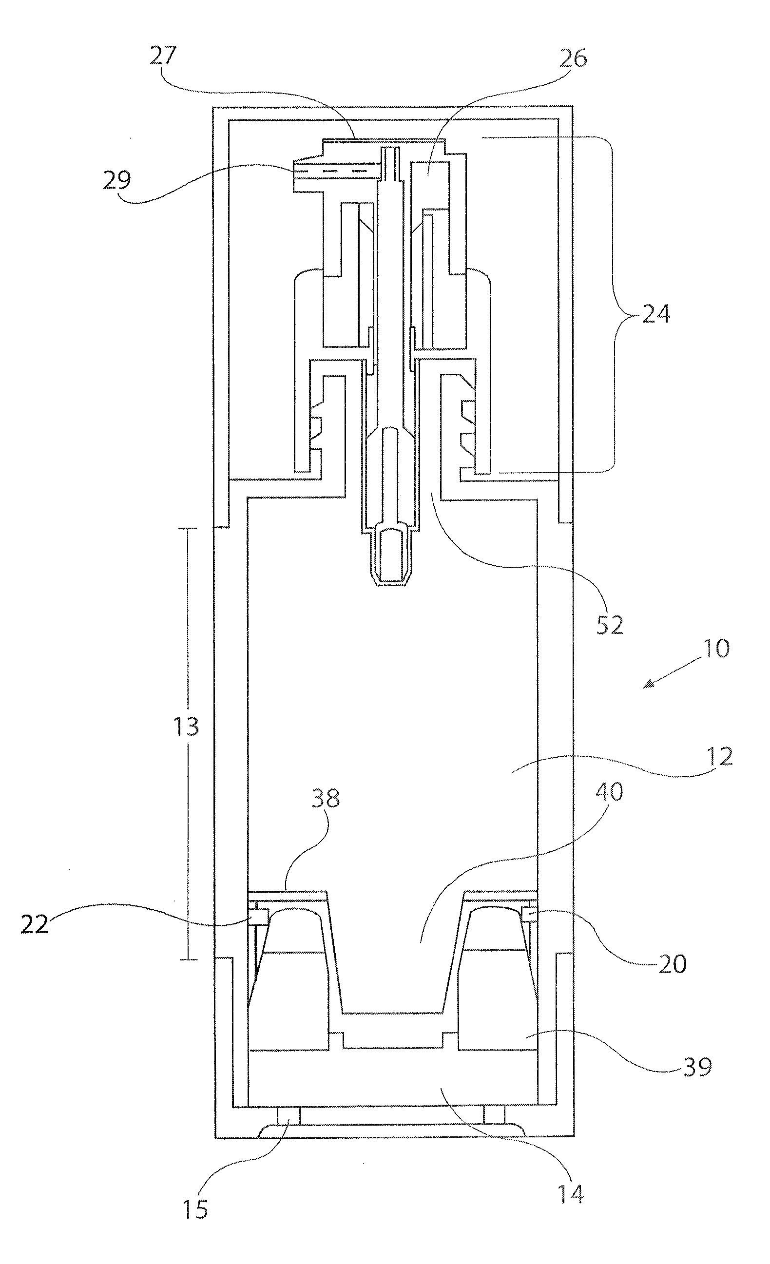
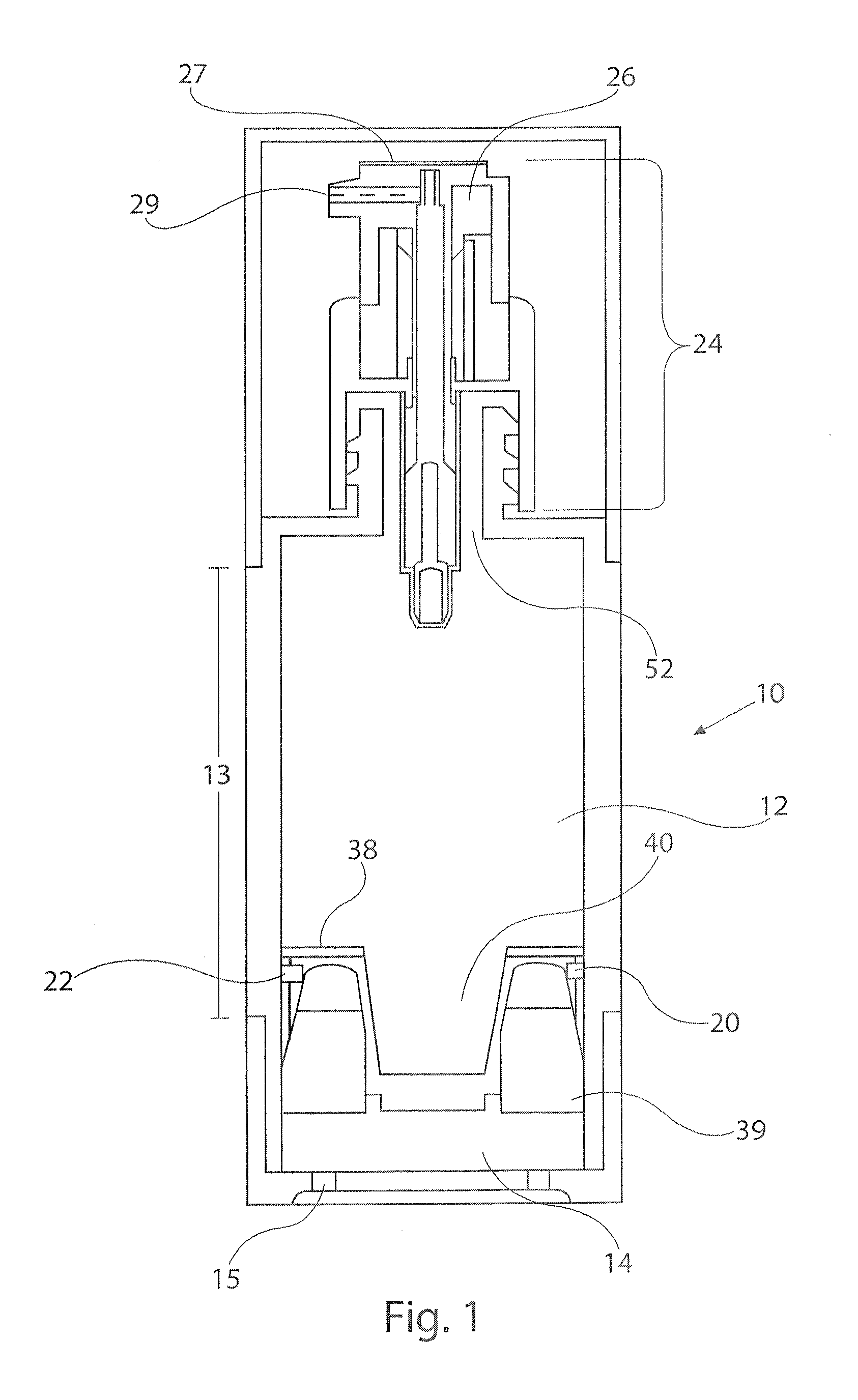
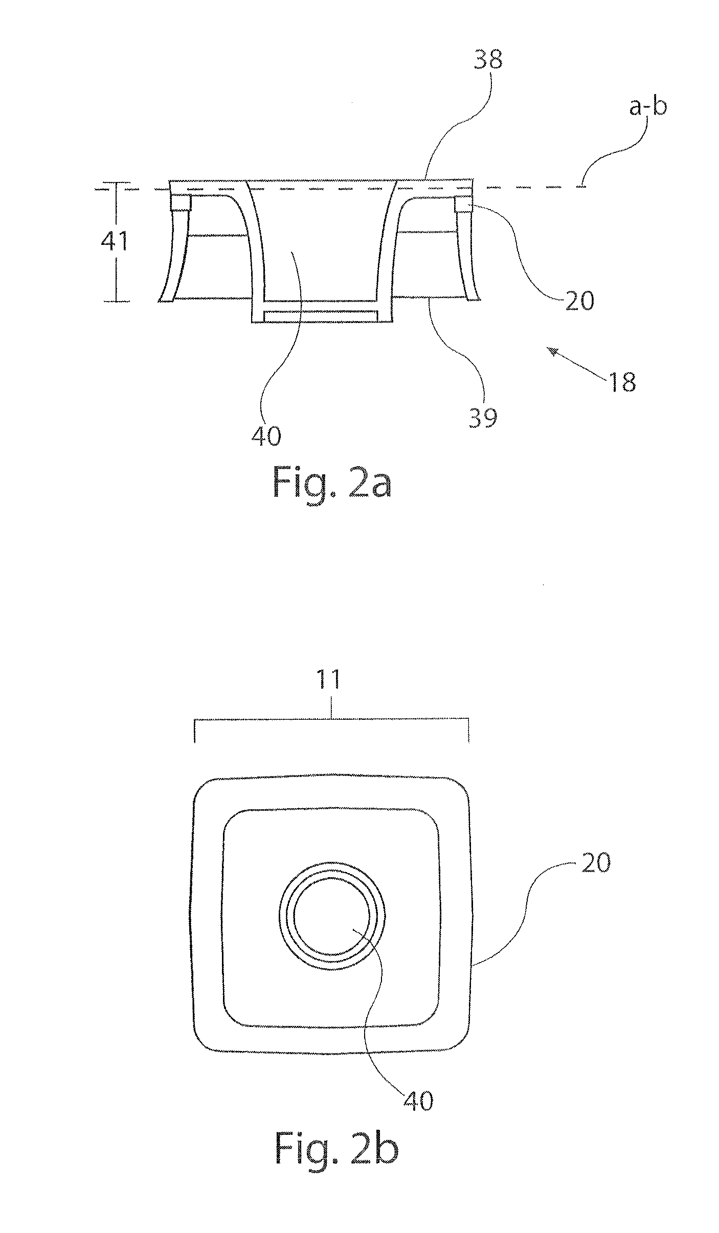
[0021]The above and other objects may be achieved using methods involving sealing the space between a piston and an interior of a chamber having a substantially uniform cross section along a height of the chamber by providing the piston with a shape that corresponds to the cross section of the chamber. The piston is provided with a channel configured to accommodate a multi-lobe seal such as an X-ring seal that is in turn sized to correspond to the size of the piston. The multi-lobe or X-ring seal is placed in the channel in the piston, and the piston is placed in the chamber. The multi-lobe or X-ring seal allows the cross section of the chamber to be substantially any shape, including a polygon having corners, provided the corners are slightly rounded, in part, to facilitate the seal. A lubricant may also be provided to the valley(s) of the multi-lobe or X-ring seal.
[0022]Alternatively, the multi-lobe or X-ring seal may be formed in-situ in the channel using a two shot or bi-injection molding process. Two shot or bi-injection molding processes have an advantage over pre-formed multi-lobe or X-ring seals in terms of ease of assembly and the ability to manufacture free-form shapes having non-uniform radii or differences in center-to-edge dimensions. A lubricant may be placed in the valley(s) of the multi-lobe or X-ring seal, such as an oil, a cream, or a small amount of the fluid to be dispersed. A release valve is also provided in fluid communication with the first chamber to release the fluid contents of the first chamber upon command. A user operates the release valve to drive the piston and expel the fluid.

Problems solved by technology

In addition to preventing reverse intake flow of “air” via the pump, an “airless pump” typically does not allow intake of any other substances to replace the volume of product pumped out of the container.
There are several problems associated with producing and using such devices.
First of all, the seal between the piston and the interior surface of the container often is insufficient.
Accordingly, any irregularity, such as a corner in a non-circular shaped container or a longitudinal weld line which produces a thickening, is detrimental to forming a leak proof seal.
Additionally, O-ring seals are subject to spiral failure.
Rapid stress-aging can cause a rupture of the O-ring to start adjacent the clearance gap.
One of the primary causes of spiral failure is slow speeds of the piston where the sliding, or running, seal friction is very high relative to the break out friction.
Pistons in airless pumps used for personal care products typically are moved a small fraction of an inch at a time over several months of use, exacerbating the problem of spiral failure in O-ring seals.
These pistons work well for applications where the container has round or cylindrical walls, however, they typically are not reliable when used for applications where the piston contact walls are a non-cylindrical surface such as a square, heart shape, triangular or other shape including free form shapes.
Such a complicated structure is difficult to manufacture and assemble and accordingly is more costly to produce.

Method used


Image

  • Airless pump dispensing system with multi-lobe ring seal
  • Airless pump dispensing system with multi-lobe ring seal
  • Airless pump dispensing system with multi-lobe ring seal

Examples


Embodiment Construction

[0032]In the following description, and for the purposes of explanation, numerous specific details are set forth in order to provide a thorough understanding of the various aspects of the invention. It will be understood, however, by those skilled in the relevant arts, that the present invention may be practiced without these specific details. In other instances, known structures and devices are shown or discussed more generally in order to avoid obscuring the invention. In many cases, a description of the operation is sufficient to enable one to implement the various forms of the invention. It should be noted that there are many different and alternative configurations, devices and technologies to which the disclosed inventions may be applied. The full scope of the inventions is not limited to the examples that are described below.

[0033]Referring initially to FIGS. 1-3, there is shown therein a particular embodiment in accordance with the present invention comprising a hollow conta...


PUM


Abstract

Method and apparatus for dispensing a fluid using a dispensing container employing an airless pump, which may employ abstract or non-cylindrical shapes. The airless pump uses a chamber enclosing a fluid with a piston comprising a surface of the chamber. The chamber has an interior volume with a substantially uniform cross section along a height of the chamber, to which the piston is conformed allowing the piston to transverse the height of the chamber. The gaps between the piston and the interior of the chamber are sealed with a multi-lobe ring seal.

Description

BACKGROUND OF THE INVENTION[0001]1. Field of the Invention[0002]The present invention generally relates to airless dispensing pumps, and more specifically, but not exclusively, concerns an airless dispensing pump that is able to efficiently pump fluids while at the same time minimizes leakage and exposure of the contents to air and contamination. The invention has particular utility in connection with airless dispensing pumps for personal care products and will be described in connection with such utility, although other utilities are contemplated.[0003]2. Description of Related Art[0004]Airless type pumps have been developed for a wide range of applications including dispensing personal care products, such as skin creams, skin lotions, toothpaste, hair gels hand lotions, face creams, wrinkle serums, acne treatments, shampoos, conditioners and liquids for a host of applications. An airless pump typically refers to a pump that provides pumping of a substance from a container in essen...

Claims


Application Information

Patent Timeline
Patent Type & Authority Applications(United States)
IPC IPC(8): B67D7/00F16J15/32B65D88/54
CPCB05B11/0048B65D83/64B65D83/0033B05B11/028
Inventor DEANS, DAVID M.
Owner ROBERTS CONTAINER CORP
Learn More