Methods and apparatus for forming a composite component

a composite component and composite technology, applied in the field of composite component forming methods, can solve the problems of most damaging the eventual properties of the component, and achieve the effect of significantly reducing the surface area of the fillet region that cannot be desired

Active Publication Date: 2012-04-12
ROLLS ROYCE PLC
View PDF3 Cites 10 Cited by
  • Summary
  • Abstract
  • Description
  • Claims
  • Application Information

AI Technical Summary

Benefits of technology

[0015]According to the present invention, there is provided a method of forming a composite component having a fillet joint, characterised in that the method comprising thermally insulating the fillet region of the component during cure, such that the fillet region is substantially the last region of the component to cure. In this manner, undesirable tensile residual stresses in the surface area of the fillet region can be significantly reduced.

Problems solved by technology

The insert may thus provide rigidity to the mould at the fillet region, where deformation of the mould is most damaging to the eventual properties of the component to be formed.

Method used


Image

  • Methods and apparatus for forming a composite component
  • Methods and apparatus for forming a composite component
  • Methods and apparatus for forming a composite component

Examples


Embodiment Construction

[0040]As discussed above, the various aspects of the present invention, both method and apparatus, may be employed singly or in combination to beneficial effect. The following detailed description discloses two exemplary embodiments of mould tooling, each of which embody some combination of the inventive aspects disclosed above. It will be appreciated that alternative combinations of inventive aspects may be considered. Particularly as regards the methods of forming components disclosed and claimed in the present specification, it will be appreciated that the moulds described in detail below represent merely one exemplary manner in which the methods may practically be employed.

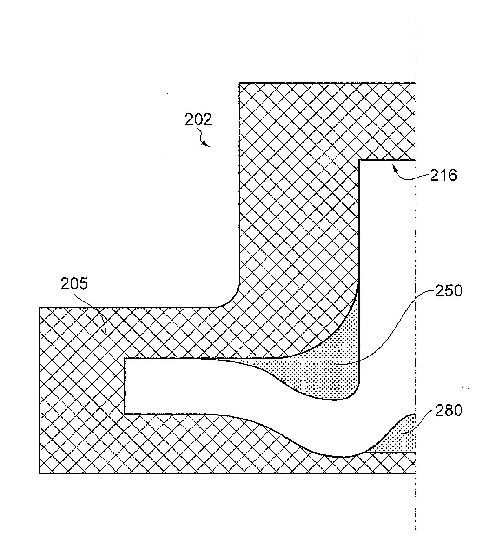
[0041]With reference to FIG. 6, a mould tooling 102 for a composite “T” joint component 108 comprises a mould body 105 having a mould cavity 116 formed therein. The mould tooling 102 is illustrated in part section, showing only one half of the tooling. It will be appreciated that the other half of the mould to...


PUM

PropertyMeasurementUnit
heataaaaaaaaaa
thermally insulatingaaaaaaaaaa
radius of curvatureaaaaaaaaaa

Abstract

A mould for a composite component having a fillet joint, the mould including a mould body having a cavity within which the component is formed, and an insert mating with the mould body and including a forming surface against which, in use, the fillet of the component fillet joint is formed. The insert may be thermally insulating and highly rigid. A method of forming a composite component having a fillet joint using a mould, the method including forcing a surface of the fillet region of the component to adopt a non constant radius of curvature while the component is inside the mould during the cure process is also provided. Additionally, a method of forming a composite component having a fillet joint that is defined between first and second legs the method including placing the legs of the component in bending during cure of the component is described.

Description

[0001]The present invention relates to methods for forming a composite component having a fillet joint, including for example composite components having “T” or “L” joints. The present invention also relates to apparatus in the form of moulds for forming such components.[0002]Organic matrix composite materials can offer significant advantages over metallic alternatives for component parts of a gas turbine engine, principally in reducing the overall weight of the engine. Many such components include joint regions in the form of a “T” or “L” having a fillet. An exemplary process for forming such components is described below, with reference to FIGS. 1 to 5.[0003]FIG. 1 illustrates one half of a lightweight mould tooling 2 for a composite “T” joint. The second half of the mould tooling 2 is a mirror image along the axis 3. The tooling 2 defines first and second legs 4, 6, of the composite “T” joint component 8 as well as a fillet region 10 between the first and second legs 4, 6. The fi...

Claims


Application Information

Patent Timeline
Patent Type & Authority Applications(United States)
IPC IPC(8): B29C45/78
CPCB29C35/002B29C35/02B29C70/54B29C70/48B29C35/0266B29C70/548
Inventor MCMILLAN, ALISON J.
Owner ROLLS ROYCE PLC
Why Eureka
Try Eureka