Laser beam generating apparatus for a laser scanning unit

a laser scanning unit and laser beam technology, applied in the direction of instruments, electrographic processes, optical elements, etc., can solve the problems of changing the volume of applied uv bonding, and affecting the quality of laser scanning equipment, so as to improve the productivity and quality of goods

Inactive Publication Date: 2006-05-04
SAMSUNG ELECTRONICS CO LTD
View PDF4 Cites 17 Cited by
  • Summary
  • Abstract
  • Description
  • Claims
  • Application Information

AI Technical Summary

Benefits of technology

[0027] According to embodiments of the present invention, since a dedicated implement which provisionally fixes the collimate lens holder in the calibration position is used together with the UV bond, assembling errors caused by change in volume of the UV bond can be prevented, thereby improving productivity and quality of goods.

Problems solved by technology

However, when the UV bond 40 is hardened by radiation of an ultraviolet ray after being applied in a liquid form, heat is generated, thereby causing change in volume of the applied UV bond.
As a result, in the process of adjusting the location of the collimate lens holder 20 with respect to an optical axis and a beam diameter and fixing the adjusted location using the UV bond 40, assembling errors may frequently occur due to the change in volume of the UV bond 40.

Method used


Image

  • Laser beam generating apparatus for a laser scanning unit
  • Laser beam generating apparatus for a laser scanning unit
  • Laser beam generating apparatus for a laser scanning unit

Examples


Embodiment Construction

[0039] Reference will now be made in detail to the embodiments of the present invention, examples of which are illustrated in the accompanying drawings, wherein like reference numerals refer to the like elements throughout. The embodiments are described below to explain the present invention by referring to the figures.

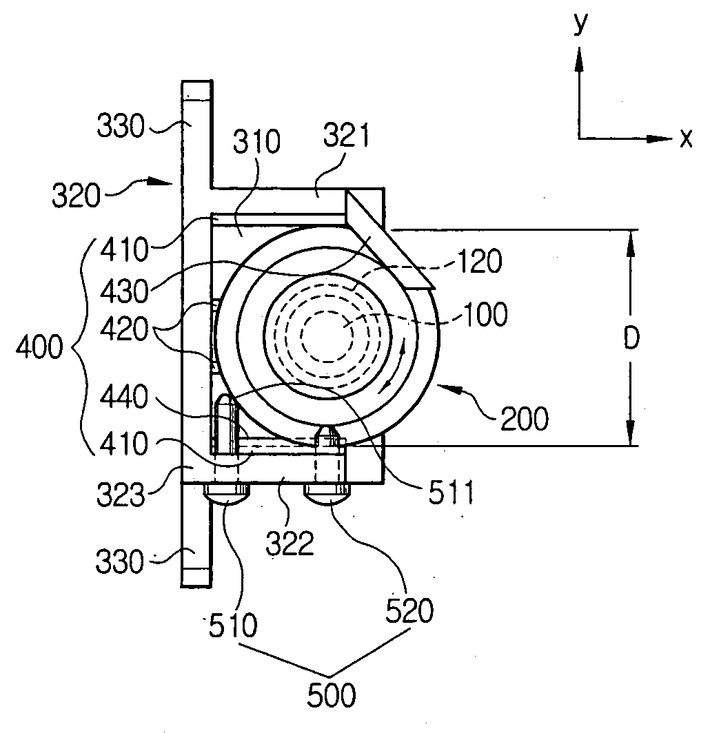
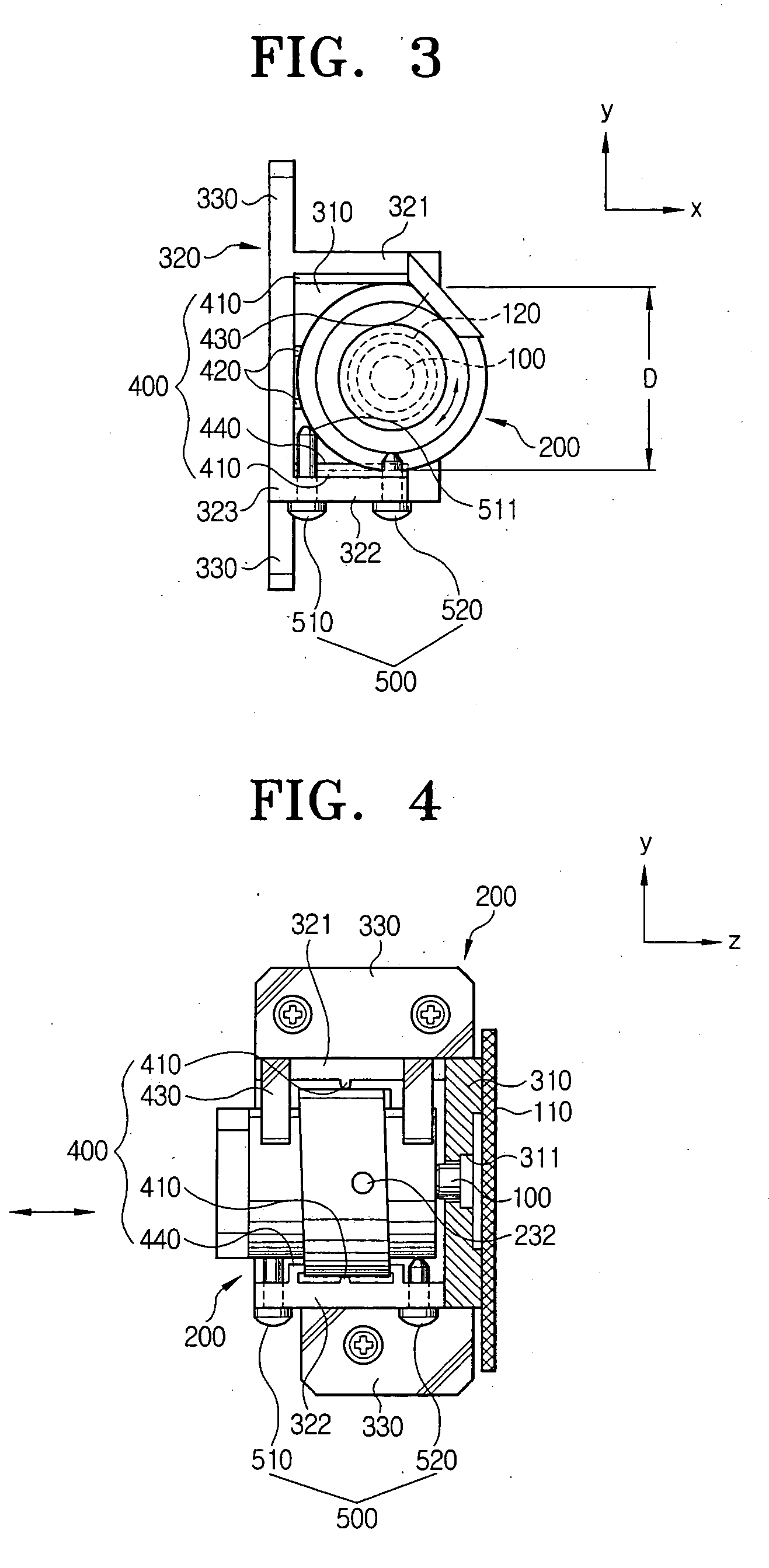
[0040] FIGS. 3 to 5 are a front view, a side view and an exploded view, respectively, of a laser beam generating apparatus according to an embodiment of the present invention.

[0041] The laser beam generating apparatus of a laser scanning unit, according to an embodiment of the present invention, includes a laser diode 100, a collimate lens 120, a collimate lens holder 200, a base 300 and a supporting means 400.

[0042] The laser diode 100 is connected to a printing circuit board 110 to irradiate a laser beam containing image information onto a photoconductive medium (not shown). The collimate lens 120 converts the laser beam emitted from the laser diode 100 into a pa...


PUM


Abstract

A laser beam generating apparatus of a laser scanning unit, including: a laser diode; a collimate lens for converting a laser beam emitted from the laser diode to a parallel light; a collimate lens holder for disposing the collimate lens on an optical axis of the laser beam; a base for mounting the laser diode and the collimate lens holder thereon; and a supporting means formed on the base to provisionally fix the collimate lens holder. Since a dedicated implement complements an ultraviolet (UV) bond to provisionally fix the collimate lens holder in the calibration position, assembling errors can be prevented although the UV bond changes in volume while being hardened, thereby improving productivity and quality of goods.

Description

CROSS-REFERENCE TO RELATED APPLICATIONS [0001] This application claims benefit under 35 U.S.C. § 119(a) of Korean Patent Application No. 2004-88598, filed Nov. 3, 2004, the entire contents of which are incorporated herein by reference. BACKGROUND OF THE INVENTION [0002] 1. Field of the Invention [0003] The present invention relates to a laser beam generating apparatus for a laser scanning unit. [0004] 2. Description of the Related Art [0005] Image forming apparatuses generally include a laser scanning unit for irradiating a laser beam on a photoconductive medium, thereby forming an electrostatic latent image. The laser scanning unit includes a laser beam generating apparatus for generating at least one laser beam of which a pattern is varied by image information. [0006]FIGS. 1 and 2 illustrate an example of a conventional laser beam generating apparatus. [0007] As shown in FIGS. 1 and 2, the laser beam generating apparatus includes a laser diode 10, a collimate lens holder 20 and a ...

Claims


Application Information

Patent Timeline
Patent Type & Authority Applications(United States)
IPC IPC(8): H01S3/10
CPCB41J2/44G02B7/025G02B26/124G03G15/0409G03G15/0435G03G2221/1636G03G21/1647G03G21/1666G03G15/04072G03G2215/0404G02B26/10G03G15/04
Inventor LEE, TAE-KYOUNG
Owner SAMSUNG ELECTRONICS CO LTD
Why Eureka
Try Eureka