Sheet processing apparatus and image forming apparatus

a technology of image forming apparatus and processing apparatus, which is applied in the directions of transportation and packaging, thin material processing, and article delivery, etc., can solve the problems of sheet obstructed alignment, unstable force for holding the sheet, and insufficient alignment of the sheet, so as to achieve appropriate alignment of the sheet and stable holding of the sh

a technology of image forming apparatus and processing apparatus, which is applied in the directions of transportation and packaging, thin material processing, and article delivery, etc., can solve the problems of sheet obstructed alignment, unstable force for holding the sheet, and insufficient alignment of the sheet, so as to achieve appropriate alignment of the sheet and stable holding of the sh

US20060097445A1Inactive Publication Date: 2006-05-11CANON KK

Image

  • Sheet processing apparatus and image forming apparatus
  • Sheet processing apparatus and image forming apparatus
  • Sheet processing apparatus and image forming apparatus

Examples


first embodiment

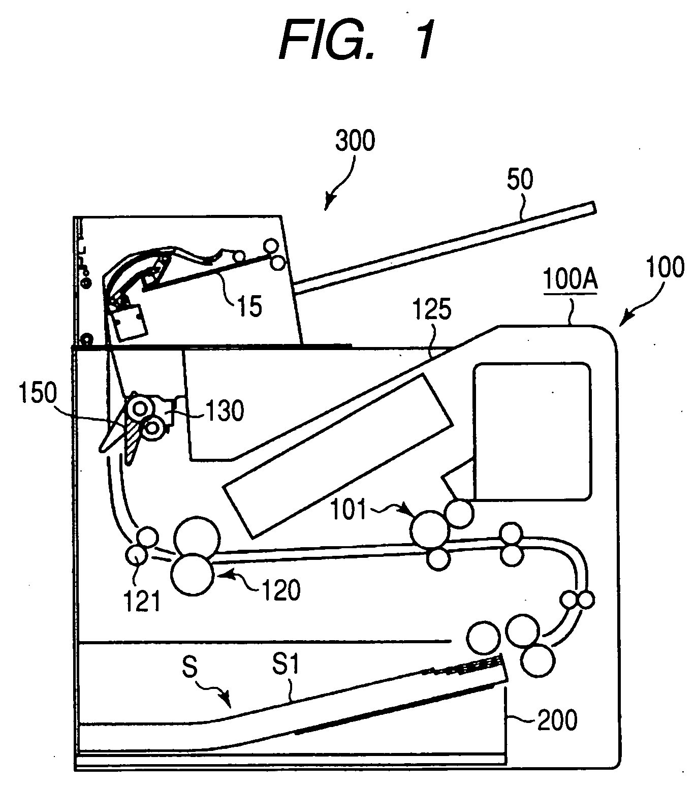
[0025]FIG. 1 is a schematic sectional view showing an overall structure of a laser beam printer which is an example of an image forming apparatus including a sheet processing apparatus according to the present invention.

[0026] In FIG. 1, a laser beam printer 100 includes a laser beam printer main body (hereinafter referred to as printer main body) 100A. The laser beam printer 100 is independently connected to a computer or a network such as a Local Area Network (LAN). The laser beam printer 100 forms (prints) an image on a sheet according to a predetermined image formation process on the basis of image information, a print signal, or the like sent from the computer or the network and discharges the sheet.

[0027] A sheet processing apparatus 300 is arranged above the printer main body 100A. After sequentially taking sheets, which are discharged to the outside of the laser beam printer 100 from the printer main body 100A, into the sheet processing apparatus 300, the sheet processing a...

second embodiment

[0053] the present invention will be explained.

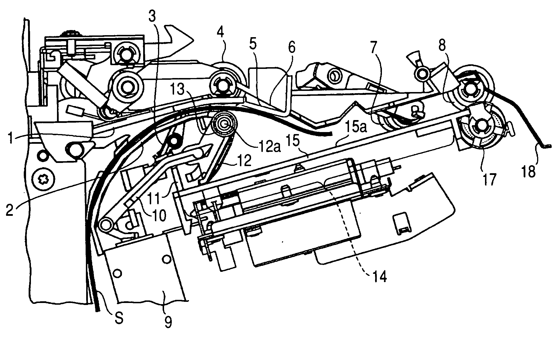
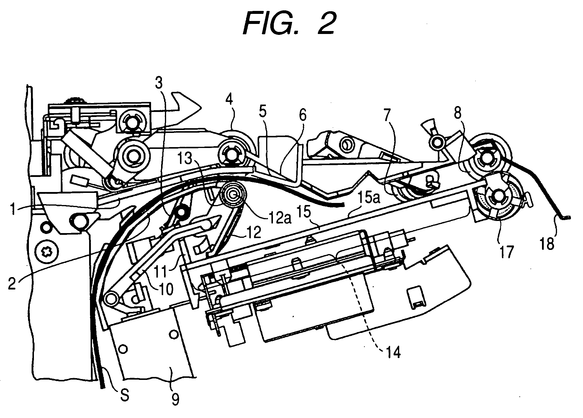
[0054]FIG. 7 is an enlarged view of a substantial part of the sheet processing apparatus 300 according to this embodiment. Note that, in FIG. 7, reference numerals and symbols identical with those of FIG. 2 denote portions identical with or equivalent to those of FIG. 2.

[0055] In FIG. 7, reference numeral 202 denotes a tip lever and 203 denotes a root lever which pivotably holds the tip lever 202. The upper guide 12 is constituted by the root lever 203 and the tip lever 202. Note that a bottom surface at a distal end portion of the tip lever 202 is planar such that the upper guide 12 can hold sheet S on a plane.

[0056] Reference numeral 201 denotes a solenoid link which transmits an operation of the solenoid 9 to the upper guide 12. The solenoid link 201 is constituted by a first lever 201a, one end of which is pivotably attached to a plunger 9a of the solenoid 9, a second lever 201b, one end of which is pivotably attached to the dista...


PUM


Abstract

A sheet conveyed to a sheet stacking portion is conveyed in a direction opposite to a sheet conveyance direction by a returning roller to bring a trailing edge of the sheet into abutment against a reference wall and regulate a trailing edge position of the sheet. A pressure portion which presses the sheet to the reference wall is pivotably provided between the returning roller and the reference wall. The pressure portion presses the sheet conveyed by the returning roller to the reference wall while urging the sheet with a first urging force and, after the sheet comes into abutment against the reference wall, is urged by the urging unit to press the sheet, the trailing edge position of which is regulated by the reference wall, with a second urging force larger than the first urging force to hold the sheet.

Description

BACKGROUND OF THE INVENTION [0001] 1. Field of the Invention [0002] The present invention relates to a sheet processing apparatus and an image forming apparatus, and more particularly to a structure of holding means for holding sheets aligned for processing. The present invention provides a sheet processing apparatus and an image forming apparatus which can stably hold sheets and appropriately align the sheets. [0003] 2. Related Background Art [0004] Conventionally, for example, as an image forming apparatus such as a copying machine, a printer, and a facsimile, there is known an image forming apparatus including a sheet processing apparatus which, in order to reduce time and labor required for binding processing and the like for sheets such as copy paper having images formed thereon, sequentially takes the sheets with images formed thereon into the image forming apparatus and selectively applies binding processing, punching processing, and the like to the sheets. As such a sheet pr...

Claims


Application Information

Patent Timeline
11 May 2006
Publication
US20060097445A1
IPC
B65H31/26
CPC
B65H31/26; B65H31/34; B65H31/36; B65H2801/27
Inventors
FUKATSU, MASAYOSHI; OGATA, ATSUSHI