Jumper device and jumper assembly

Inactive Publication Date: 2006-06-08
ASUSTEK COMPUTER INC
View PDF11 Cites 3 Cited by
  • Summary
  • Abstract
  • Description
  • Claims
  • Application Information

AI Technical Summary

Benefits of technology

[0013] As mentioned above, each of the jumper device and the jumper assembly of the invention has a connecting member to prevent the jumper device from being lost. Compared to the prior art, the jumper device and the jumper assembly of the invention utilize a connecting member having a connecting portion to fix the jumper at a predetermined position. Consequently, when the jumper of the invention is not in use, it still can be fixed at the predetermined position. Therefore, the user does not have to worry about the loss of the jumper device, and the problem of incapable of starting the computer or even the damage of the mainboard owing to the loss of the jumper device can be eliminated. Furthermore, when the user wants to use the jumper device at the next time, he / she can easily find the jumper device because the jumper device is fixed at the predetermined position. In addition, the mainboard manufacturer can provide the jumper device having the connecting member and the assembly of the jumper device so as to decrease the number of mainboards to be sent back to the original manufacturer due to the loss of the jumper, and thus decrease the transportation, manpower and material costs for maintenance.

Problems solved by technology

If the manufacturer manufactures many kinds of mainboards to meet various conditions, the cost efficiency is low.
However, once the jumper 10 is removed from the mainboard 20, the jumper 10 tends to be lost and cannot be easily found because the size of the jumper 10 is very small.
As a result, a small jumper 10 brings inconvenience for the user and the manufacturer if it is lost.

Method used


Image

  • Jumper device and jumper assembly
  • Jumper device and jumper assembly
  • Jumper device and jumper assembly

Examples


Embodiment Construction

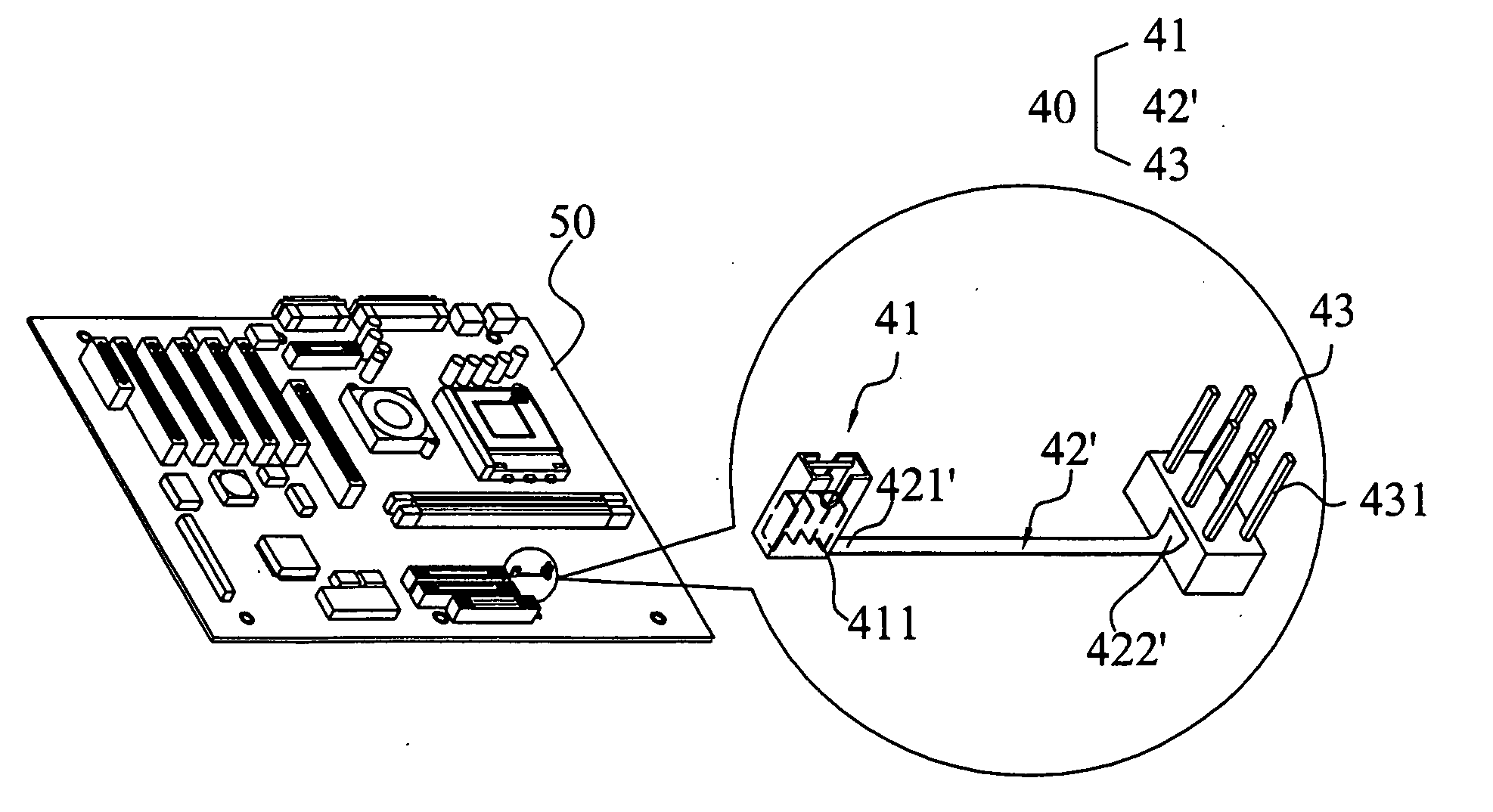
[0021] The present invention will be apparent from the following detailed description, which proceeds with reference to the accompanying drawings, wherein the same references relate to the same elements.

[0022] First, jumper devices according to a preferred embodiment of the invention will be described with reference to FIGS. 2 and 3.

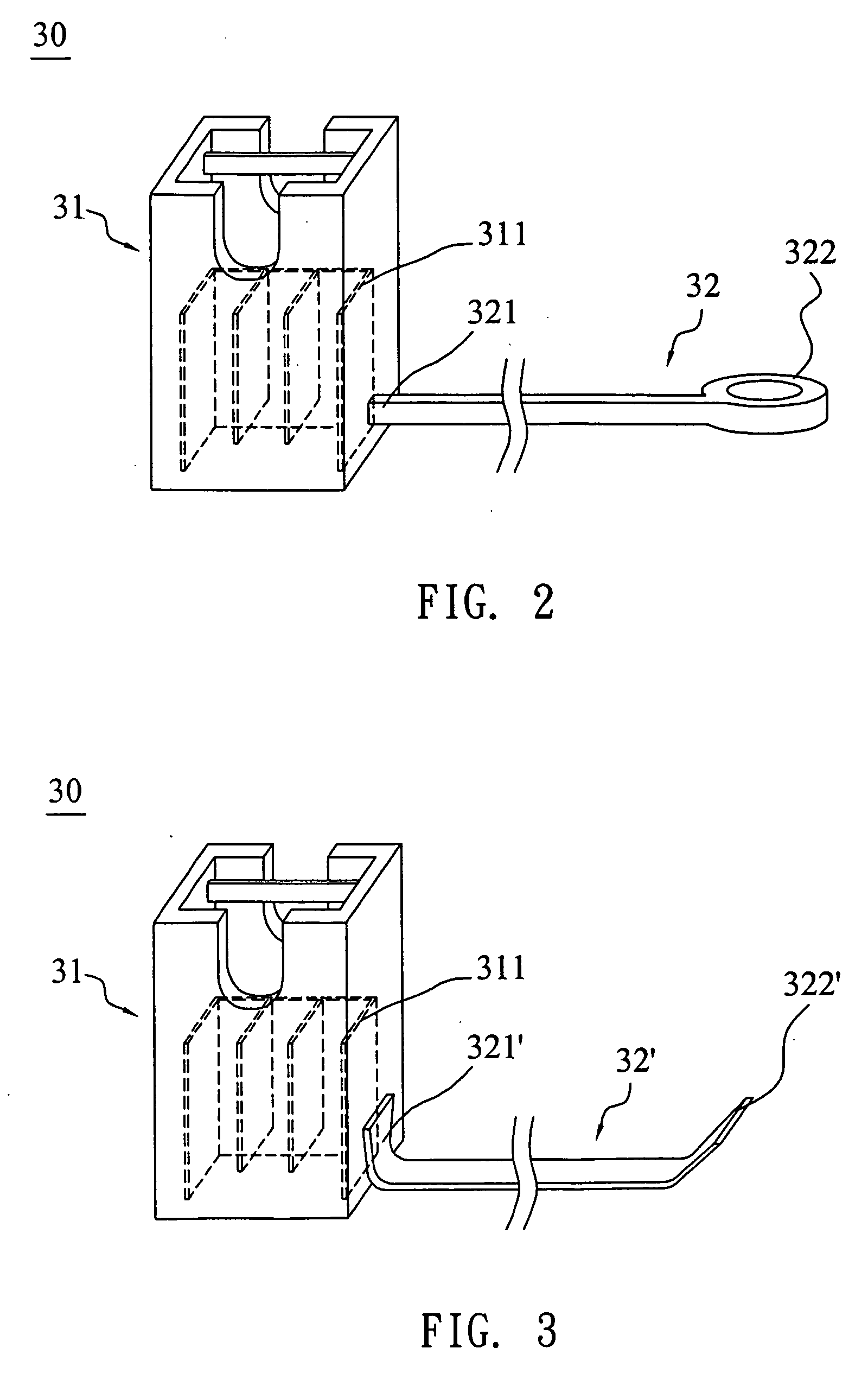
[0023]FIG. 2 is a schematic illustration showing a jumper device according to the embodiment of the invention. The jumper device 30 includes a jumper 31 and a connecting member 32.

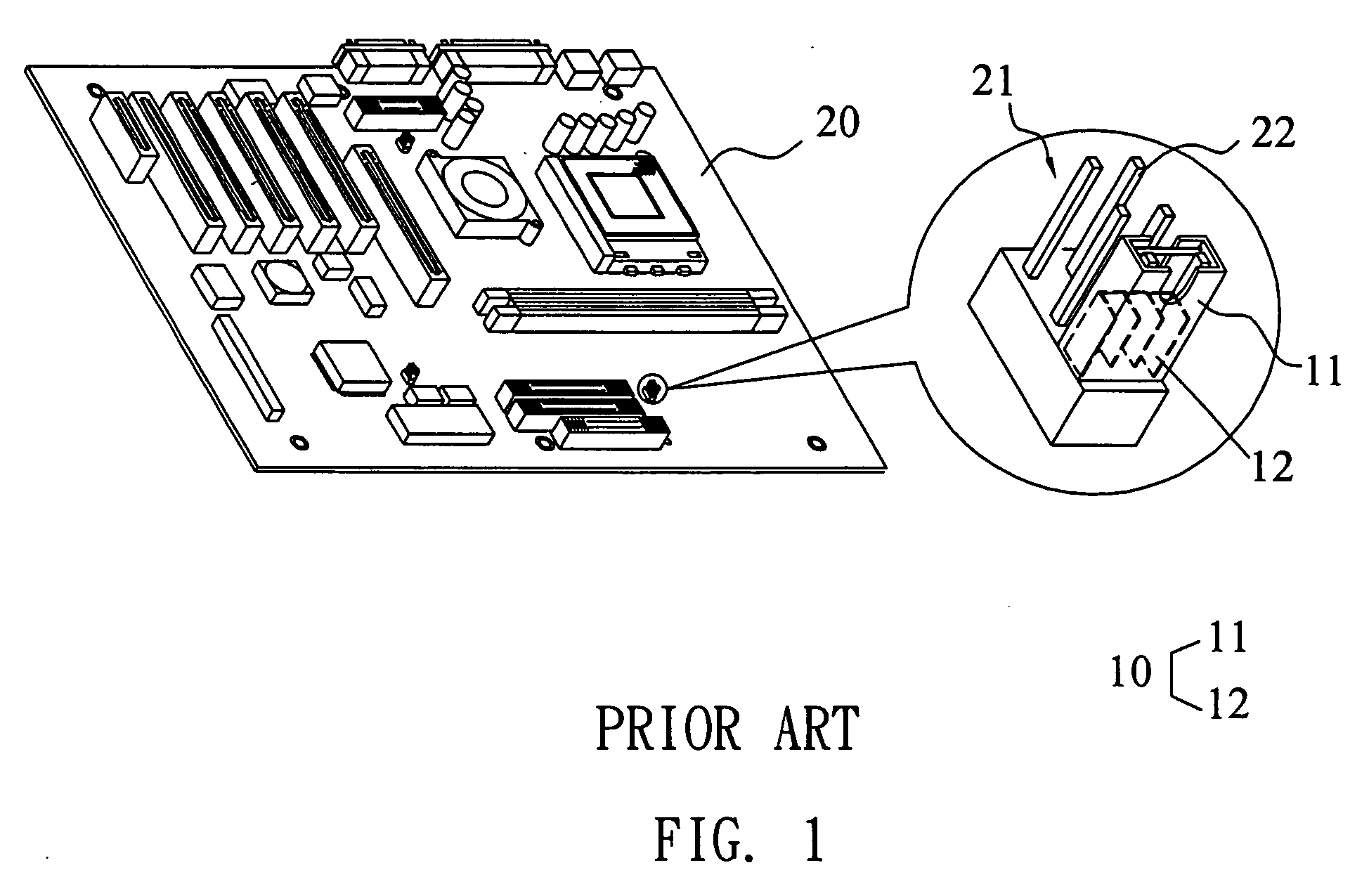
[0024] The casing of the jumper 31 is made of an insulation material such as a plastic material. The jumper 31 has a conductive jumper metal 311 inside the casing. When the jumper 31 is used, the jumper 31 is inserted by a pin header. At this time, the conductive jumper metal 311 of the jumper 31 can contact two pins of the pin header such that the pins are connected to each other through the conductive jumper metal 311 to form a close circuit (ON state), and the circuit of ...


PUM


Abstract

A jumper device includes a jumper and a connecting member. In this case, one end of the connecting member connects with the jumper device. Another end of the connecting member has at least one connecting portion. A jumper assembly including the jumper device is also provided.

Description

BACKGROUND OF THE INVENTION [0001] 1. Field of Invention [0002] The invention relates to a jumper device, and more particularly to a jumper device used in an electrical device. [0003] 2. Related Art [0004] A jumper is a tool for changing the circuit. In a computer, for example, a mainboard often has to fit with various electrical elements with different specifications, such as CPUs (Central Processing Units) with different speeds or different output voltages. If the manufacturer manufactures many kinds of mainboards to meet various conditions, the cost efficiency is low. It is possible to modify one trace on the mainboard to meet two different CPUs. In such a case, the jumper may be used in a simple way by only pulling up the jumper from the pin header of the mainboard, changing the position of the jumper, and then inserting the jumper into another position of the pin header. Consequently, the clock of the processor may be set, or the hard disk can be modified from a master to a sla...

Claims


Application Information

Patent Timeline
IPC IPC(8): H01R31/08
CPCH01R31/08H05K3/222H05K2201/10363
Inventor HUANG, JEN-YUAN
Owner ASUSTEK COMPUTER INC
Why Eureka
Try Eureka