Carburetor

a carburetor and rotor body technology, applied in the field of carburetor, can solve the problem of large overall size, and achieve the effect of reducing the overall size of the carburetor in the direction of the axis of rotation, reducing the overall size of the carburetor, and facilitating the installation spa

Active Publication Date: 2006-06-22
ANDREAS STIHL AG & CO KG
View PDF17 Cites 18 Cited by
  • Summary
  • Abstract
  • Description
  • Claims
  • Application Information

AI Technical Summary

Benefits of technology

[0012] Due to the special configuration of the portion of the mixture channel and/or of the air channel that is disposed in the vicinity of the throttle element, it is possible to make better use of the installation space that is available. As a result, the overall size of the carburetor can be reduced.
[0013] Advantageously, the height, as measured in the direction of the axis of rotation, of the channel portion having the non-circular flow cross-section is smaller than the width, as measured perpendicular to the axis of rotation. As a result, the overall size of the carburetor in the direction of the axis of rotation can be reduced. A good utilization of the installation space can be achieved as a result of the mixture channel and the air channel in the carburetor being separated from one another by a partition. This partition is in particular fixed in position on the carburetor. A straightforward configuration can be achieved if a partition section is fixed in position on the throttle element. The partition section can, in particular, be monolithically fo...

Problems solved by technology

The drawback of the known carbureto...

Method used


Image

  • Carburetor
  • Carburetor
  • Carburetor

Examples


Embodiment Construction

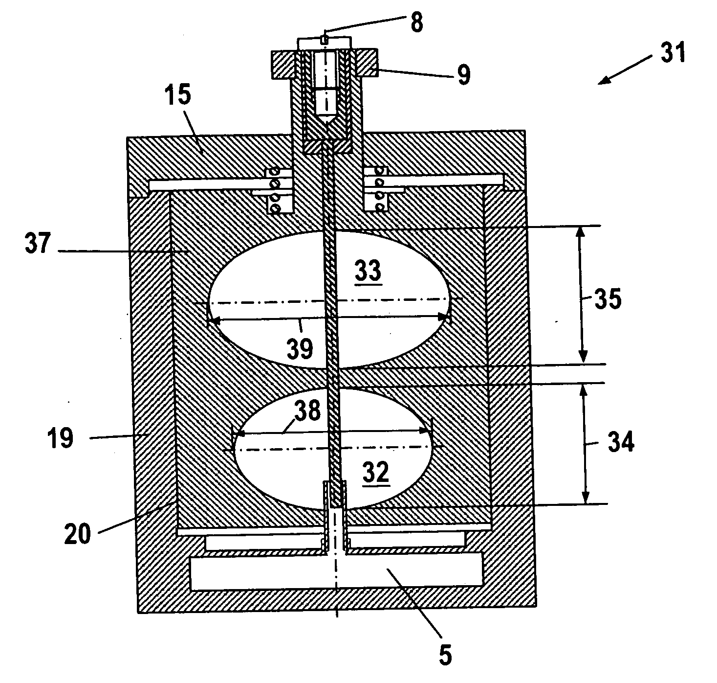
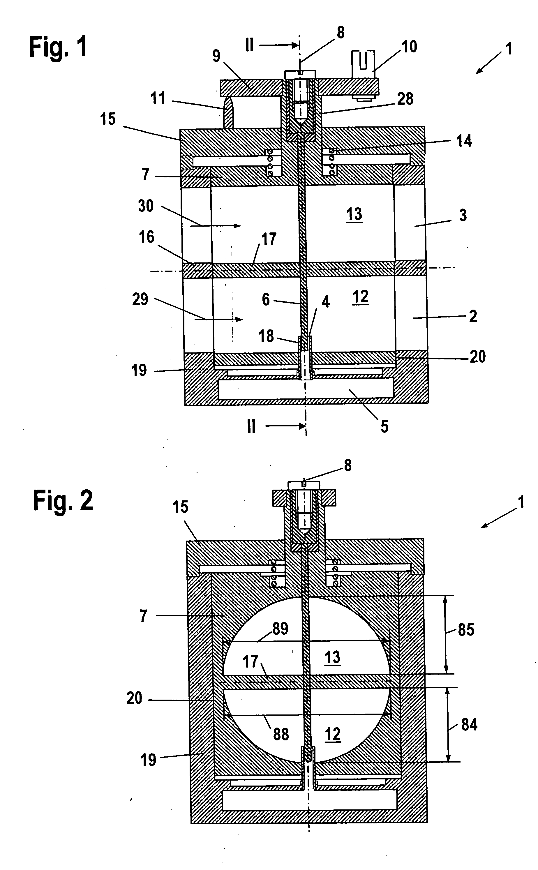
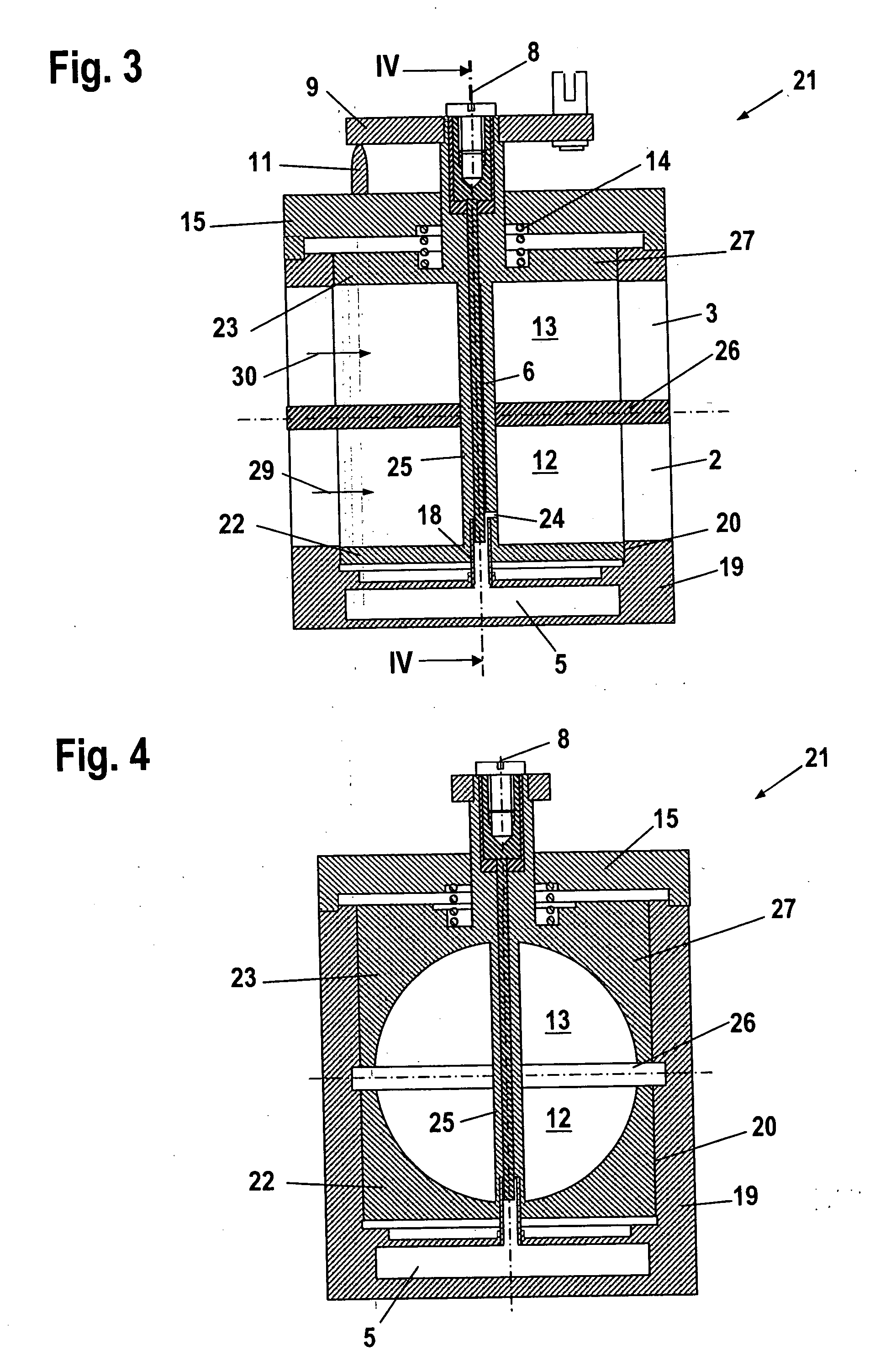
[0018] Referring now to the drawings in detail, the carburetor 1 shown in FIG. 1 has a housing 19 in which are formed a mixture channel 2 and an air channel 3. The housing 19 is closed off by a cover 15. Formed in the housing 19 is a receiving means 20 in which the cylinder 7 is mounted so as to be rotatable about an axis of rotation 8 and so as to be displaceable in the direction of the axis of rotation 8. The cylinder 7 is yieldingly mounted relative to the cover 15 by a spring 14. Formed in the cylinder 7 are a mixture channel portion 12 and an air channel portion 13. The axis of rotation 8 extends through both of the channels 2, 3 perpendicular to the direction of flow 29, 30 in the channels. In this connection, the axis of rotation 8 extends perpendicular to a partition 16 that separates the two channels 2, 3 from one another. However, the axis of rotation 8 can also extend at an angle of less than 90° relative to the partition 16. Disposed in the housing 19 is a fuel reservoir...


PUM

PropertyMeasurementUnit
Flow rateaaaaaaaaaa
Widthaaaaaaaaaa
Heightaaaaaaaaaa

Abstract

A carburetor comprising a mixture channel and an air channel that are separated from one another, wherein a fuel opening opens into the mixture channel. A throttle element is rotatable about an axis of rotation that extends transverse of the direction of flow in the mixture channel and in the air channel and extends through both channels. As a function of its position, the throttle element throttles a flow cross-section of the mixture channel and the air channel. The flow cross-section of a portion of the mixture channel and/or of the air channel has a non-circular shape in the vicinity of the throttle element.

Description

[0001] The instant application should be granted the priority date of Dec. 21, 2004, the filing date of the corresponding German patent application 10 2004 063 397.4. BACKGROUND OF THE INVENTION [0002] The present invention relates to a carburetor, especially for a two-stroke engine in a manually-guided or portable implement such as a power saw, a brush cutter, a cut-off machine, or the like. [0003] A cylinder-type carburetor is known from EP 1 098 084 A1, according to which a portion of the mixture channel is formed in a cylinder, which acts as a throttle element. It is also known to embody such cylinder-type carburetors in such a way that the cylinder extends through not only the mixture channel but also the air channel of a scavenging two-stroke engine and controls both channels. The drawback of the known carburetors is that they have a large overall size. [0004] It is an object of the present application to provide a carburetor of the aforementioned general type that has a small...

Claims


Application Information

Patent Timeline
IPC IPC(8): F02M5/08
CPCF02B63/02F02B2075/025F02D9/104F02M9/08Y10S261/01
Inventor RAFFENBERG, MICHAEL
Owner ANDREAS STIHL AG & CO KG
Why Eureka
Try Eureka