Router device and communication method

Inactive Publication Date: 2006-11-02
PANASONIC CORP
View PDF7 Cites 4 Cited by
  • Summary
  • Abstract
  • Description
  • Claims
  • Application Information

AI Technical Summary

Benefits of technology

[0017] Meanwhile, a communication method in a seventh form of the invention is a communication method comprising: a step of transmitting a packet destined for a communication device in an external network, from a radio terminal device within a same local network to a router device; a step of detecting a connection state of between the router device and the base station of the external network when the router device received the packet; and a step of transferring the packet to the base station in a case of being connected with the base station, and transferring the packet according to a routing table in a case not connected to the base station. This makes it possible to transfer a packet to abase station external of the local network. Where connected to the base station external of the local network, a packet can be transferred preferentially to the external base station, thus providing the operation that a packet can be transferred to the opposite of communication via an external-connection router device intended by the terminal device in the local network.
[0018] Meanwhile, a communication metho

Problems solved by technology

However, the cellular telephone does not always transfer a received packet to the external network.
Namely, there is a problem that

Method used


Image

  • Router device and communication method
  • Router device and communication method
  • Router device and communication method

Examples


embodiment 1

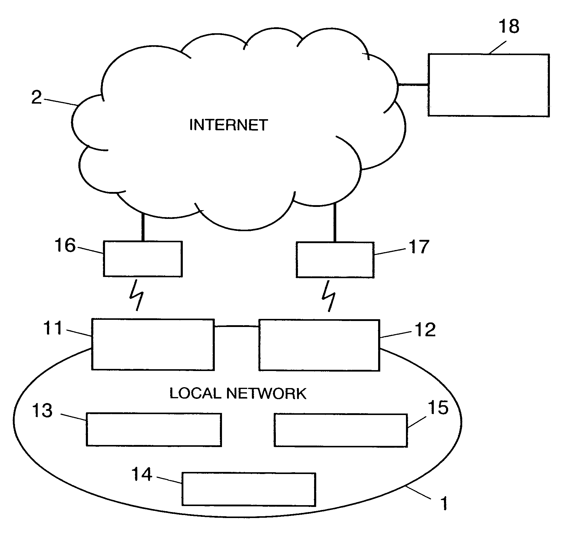
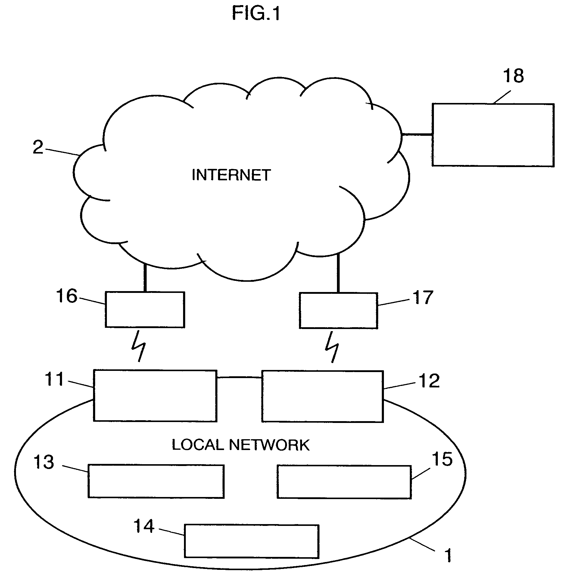
[0038]FIG. 1 is a configuration diagram of a radio communication system in embodiment 1 of the present invention. In FIG. 1, the radio communication system includes a local network 1 constituted by a plurality of radio terminal devices 13, 14, 15 and external-connection router devices 11, 12, the Internet 2, base stations 16, 17, and external terminal device 18. The external-connection router device 11, 12 has at least one radio interface to have communication with a base station external of the local network. The radio terminal device 13, 14, 15 has at least one radio interface. The base station 16, 17 has at least one radio interface, thus being connected to the Internet. The external terminal device 18 is a communication device connected to the Internet.

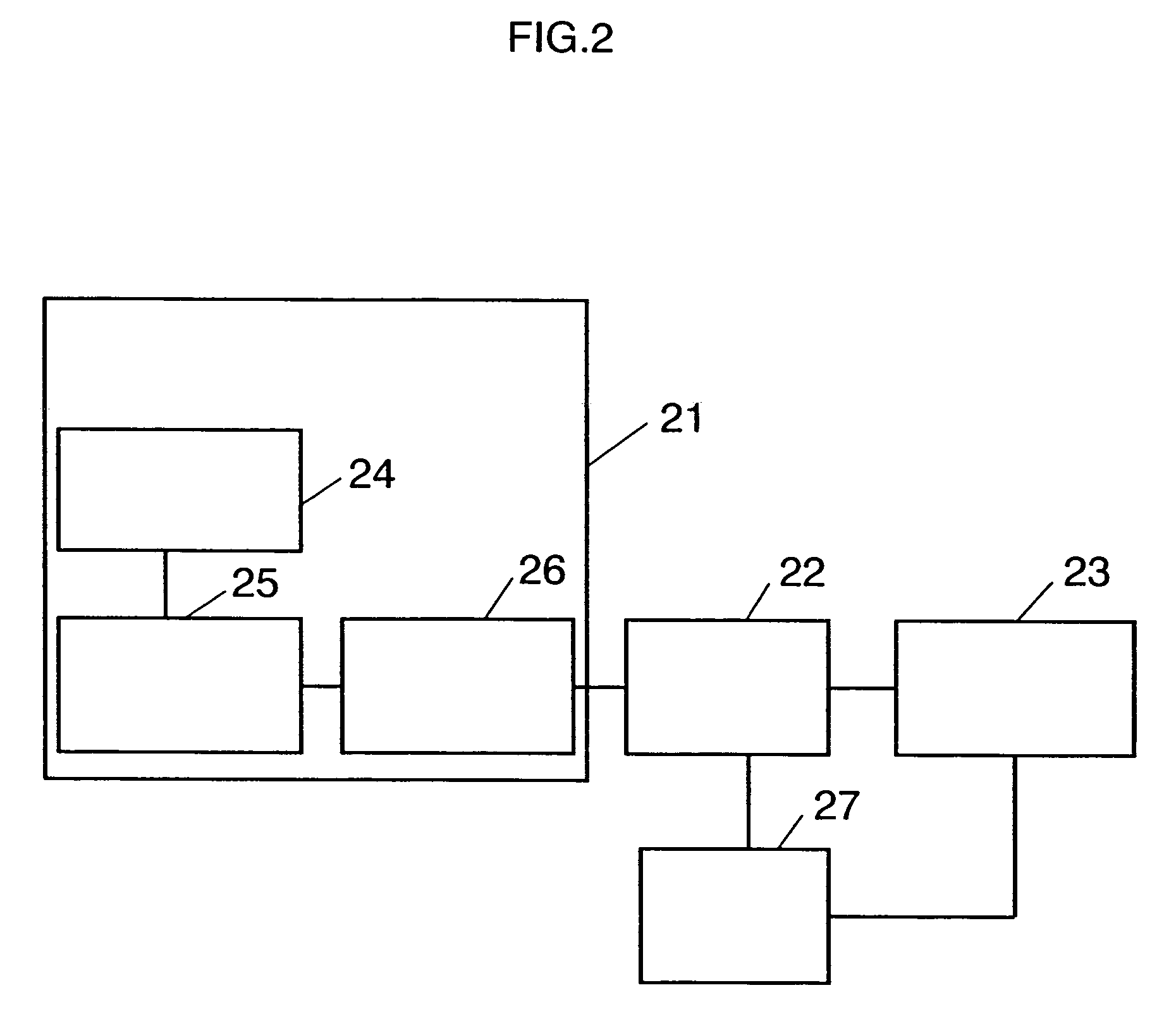
[0039] The radio terminal device 13 is now explained. The other radio terminal devices 14, 15 are similar in configuration and operation to the same.

[0040]FIG. 2 is a configuration diagram of the radio terminal device 13. In FIG...

embodiment 2

[0067]FIG. 9 is a diagram showing a configuration of an external-connection router device in embodiment 2 of the invention. In FIG. 9, the difference from embodiment 1 lies in the provision of a connection instructing section 91.

[0068] The connection instructing section 91 is to instruct a connection to a base station depending upon the information of whether or not connection is possible with the external base station 16.

[0069] The operation of the external-connection router device in this embodiment is now explained by using a flowchart of FIG. 8.

[0070] In FIG. 8, the external-connection router device in this embodiment is different from the external-connection router device in embodiment 1 in that connection is tried with the base station when not connected to the base station. Namely, the operation at steps S801 to S806 is similar to that at steps S401 to S406 of embodiment 1.

[0071] When not connected with the external base station 16, the connection instructing section 91 c...

embodiment 3

[0075]FIG. 14 is an configuration diagram of a radio communication system in the present embodiment. In FIG. 14, the difference from embodiment 1 lies in that a home agent device 1401 is provided.

[0076] To this home agent device 1401 is to be transmitted a packet (binding update) for registering a pair of movement destination address and home address by the external-connection router device 11, 12 when there is a movement of a local network to which the external-connection router device 11, 12 belongs. The home agent device 1401, in case a pair of home address and movement destination address of the external-connection router device 11, 12 is registered in a cache (binding cache), transfers all the packets thereafter transmitted destined for the home address to the external-connection router device 11, 12 through utilization of an IPv6 tunnel.

[0077] The configuration of the external-connection router device in this embodiment is now shown in FIG. 12. In FIG. 12, the difference fro...


PUM


Abstract

A router device includes a lower-layer information acquisition section for acquiring connection information of whether or not connected with a base station in an external network from a lower layer, and a route judgment section for transferring the received packet to the base station in the case of being connected with the base station and judging a transfer destination by looking up a routing table in the case of not being connected with the base station, when receiving a packet destined for a terminal in an external network from a radio terminal device in a same local network. Because the received packet is transferred to the base station during connection with the base station, the packet can be transferred to the external via the router intended by the terminal. Furthermore, the load in the local network can be reduced.

Description

TECHNICAL FIELD [0001] The present invention relates to a router device and communication method in a local network constituted by a plurality of radio terminal devices and a plurality of router devices for communication with the external terminal device existing on the Internet. BACKGROUND ART [0002] Conventionally, in a communication system using IP (Internet protocol), when a certain local network is connected to an external network, such as the Internet, through a plurality of router devices (hereinafter, referred to as external-connection router devices), in the case that a radio terminal device within the local network communicates with an external terminal device of the external network via a predetermined external-connection router device, there is a possibility that a packet is transferred to different external-connection router device in the local network and then transferred from the transferred external-connection router device to the external terminal device. [0003] For...

Claims


Application Information

Patent Timeline
IPC IPC(8): G06F15/173H04W16/26H04B7/24H04L12/701H04W40/02H04W76/02H04W80/04
CPCH04L45/22H04L45/34H04L45/54H04W80/04H04W40/22H04W40/248H04W40/36H04W40/02
Inventor FUNABIKI, MAKOTOMATSUMOTO, TAISUKEIKEDA, SHINKICHIKOBAYASHI, HIROKAZUKUMAZAWA, MASAYUKIKAWAHARA, TOYOKI
Owner PANASONIC CORP
Why Eureka
Try Eureka