Apparatus and method for moving and placing granulate material

a technology of granulate and apparatus, applied in the field of apparatus and method for moving and placing granulate, can solve the problems of heavy equipment that cannot be driven over the pad (and lines and bars), interfere with the use of heavy equipment, extreme wear and tear of these abrasive materials to these systems, etc., and achieves the effect of avoiding damage to the site, suitable sealing and short tim

Inactive Publication Date: 2007-01-25
AIR PUMP HLDG LLC
View PDF14 Cites 0 Cited by
  • Summary
  • Abstract
  • Description
  • Claims
  • Application Information

AI Technical Summary

Benefits of technology

[0010] In light of the aforementioned problems associated with the prior devices and methods, it is an object of the present invention to provide an Improved Apparatus and Method for Moving and Placing Granulate. It is an object that the present invention provide a portable, self-contained apparatus capable of discharging granulate into hard-to-reach areas, as well as providing assistance in covering vast open areas with granulate in a short time. It is a further object that the device and method permit the application of granulate into areas that are normally inaccessible and would require many hours of human labor, and thereby potentially avoiding damage to the site that might be incurred if employing a prior method and device. It is a still further object that the present invention serve to provide discharge of granulate near or adjacent to retaining walls and underneath concrete flatwork.
[0011] In an aspect of the improved version of the present invention it provides A rotary air lock pump mechanism having: a) a material feed bowl with a plurality of chambers, the bowl being configured for rotational movement around a central axis of the bowl and a power source to rotate the bowl about the axis; b) a collection barrel positioned over an open end of the bowl with a central axis of the barrel being congruent with the central axis of the bowl, the barrel remaining fixed while said bowl rotates about the central axis, the barrel directing flowable material deposited into exposed ends of the chambers of the bowl; c) an air intake material ejection manifold that when positioned in a receiving recess on the barrel is serially presented to an open end of each chamber of the bowl as the bowl is rotated about the central axis and wherein when air is injected into an air receiving portion of the manifold it is injected into a chamber of the bowl being presented to the manifold and thereby causing flowable material deposited in the chamber to be ejected out through a material ejection portion of the manifold; d) a wear gasket positioned between a first side of a face plate of the manifold and the bowl, the gasket facilitating smooth rotation of the bowl; e) a pressure mechanism engagedly positioned against a second side of the face plate to assure even wear of the wear gasket and to thereby maintain a suitable seal between the face plate of the manifold and the bowl; and f) wherein as the bowl rotates flowable material is deposited through the barrel into a portion of the chambers the ends of which are exposed in the barrel and as each chamber is serially presented to the manifold, by rotation of the bowl, the flowable material is ejected by the manifold.
[0012] In yet another aspect of the present invention it provides a material handling mechanism having: a) a loading hopper with a first opening at a top end for receiving flowable material and a second opening at a bottom end for collecting and directing flowable material placed in the first opening; b) a compactor drive apparatus located below and adjacent to the second opening of the second opening of the hopper, the compactor drive apparatus forming the flowable material from the hopper into a steady and even stream; c) a rotary air lock pump mechanism for receiving the steady even stream created by the compactor drive apparatus, the rotary air lock pump mechanism having appropriate sealing and wear mechanisms to facilitate operation and prevent leakage of flowable material and even wear of moving parts; and d) a long flexible conduit connected to a material ejection conduit of the rotary air lock pump mechanism to place the flowable material in a pre-selected location. In a further aspect of the present invention it includes a mechanism to cool pressurized air being injected into the rotary air pump.

Problems solved by technology

What has been a common problem has been moving the granulate from place to place when a dump truck and / or cranes and mechanical shovels do not have easy access.
As such, heavy equipment cannot be driven over the pad (and lines and bars) because the lines and bars (and vapor barrier) would be disturbed.
These perimeter forms also interfere with the use of heavy equipment to load the granulate into the pad.
An on going problem experienced by systems used for placing flowable material, in particular materials like sand and gravel, is the extreme wear and tear these abrasive materials cause to these systems.
These abrasive materials rapidly break down and even destroy the parts of the handling systems.
Additionally, even with various improvements a significant amount of inefficiencies exist in currently available systems.
Leaks caused by the wear and tear of various parts of the system reduce significantly the operational characteristics of these systems.
Additionally, problems still exist and significant improvements can still be made to improve the operational characteristics of these systems.

Method used


Image

  • Apparatus and method for moving and placing granulate material
  • Apparatus and method for moving and placing granulate material
  • Apparatus and method for moving and placing granulate material

Examples


Embodiment Construction

[0039] The following description is provided to enable any person skilled in the art to make and use the invention and sets forth the best modes contemplated by the inventors of carrying out their invention. Various modifications, however, will remain readily apparent to those skilled in the art, since the generic principles of the present invention have been defined herein specifically to provide an Improved Apparatus and Method for Moving and Placing Granulate.

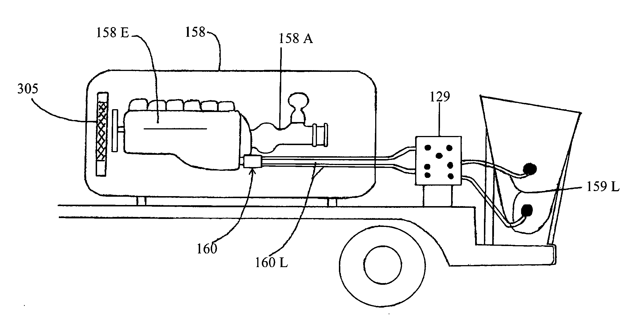
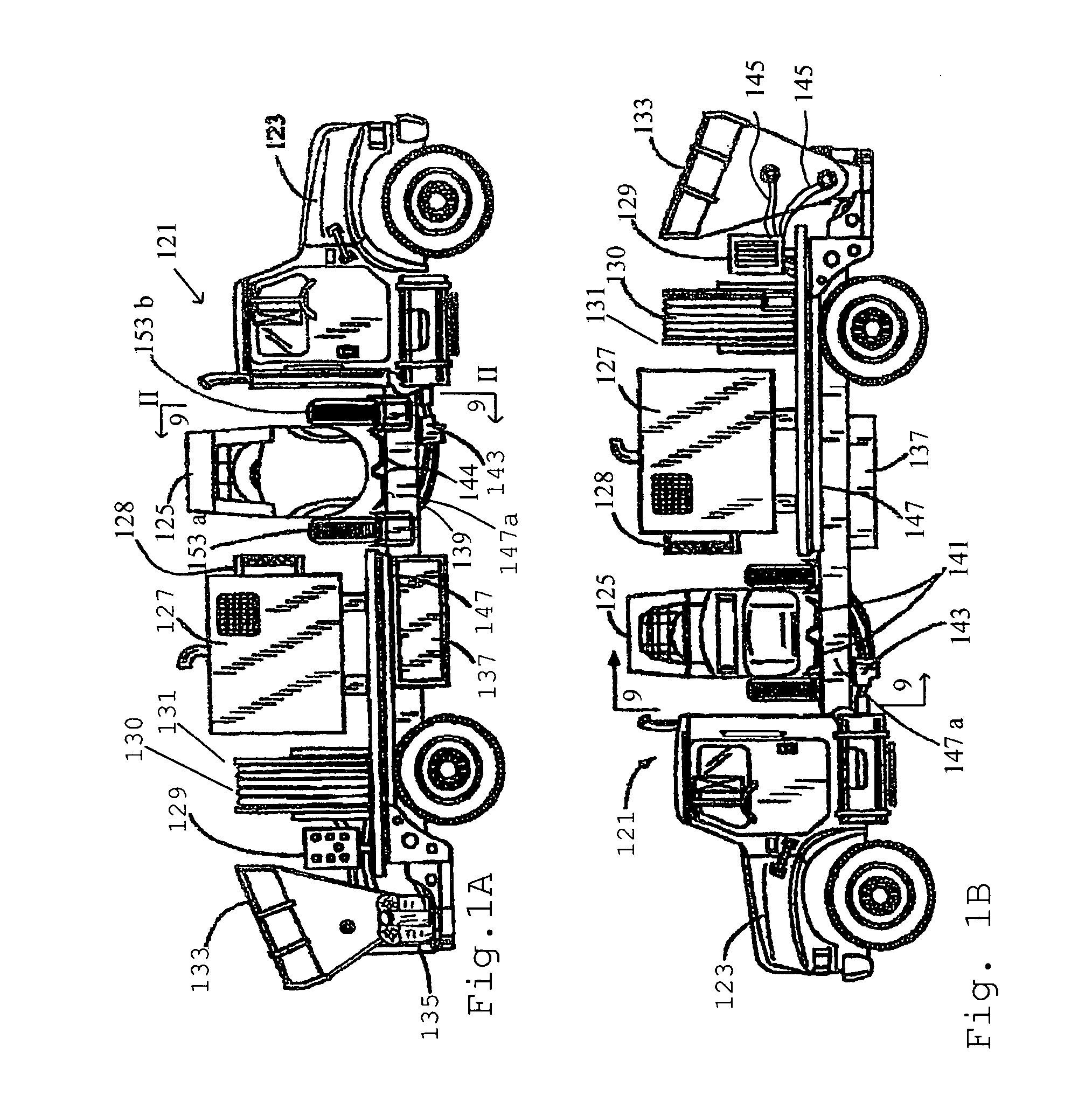
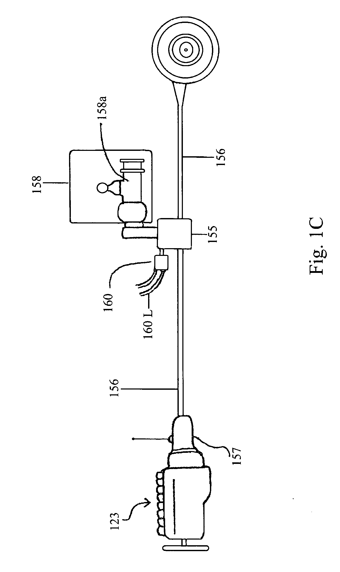
[0040]FIG. 1A and FIG. 1B are views of both sides of an improved self-propelled granulate application system of the present invention. In one preferred embodiment the system is configured on a flatbed truck 121. In FIGS. 1A and 1B the truck 121 has the typical set up with it motor 123 located in the front. The unit also includes the following viewable on both sides of the truck: a tractor loader 125, air compressor 127, air cooler 128, for cooling air leaving compressor 127, control panel 129, pump hose 131 on a hydraulic d...


PUM


Abstract

A method and system are disclosed for moving and placing in hard to reach locations granular and other particulate material such as sand, gravel, earth and similar materials. The system includes an improved auger for moving the material and an improved rotary airlock mechanism designed to withstand the abrasive action of the particulate material and at the same time move the material several hundred feet through a flexible conduit for placement in a pre-designated location. A system and apparatus is also disclosed for transporting on one vehicle all of the devices needed at a remote site for operation the particulate placement system, including a front loader.

Description

CROSS REFERENCE TO RELATED APPLICATION [0001] This application is a Continuation-in-Part of application Ser. No. 10 / 340,214, filed 9 Jan. 2003, now U.S. Pat. No.______, issued ______06, and the disclosure of which is incorporated herein by reference to the extent necessary for a full enabling disclosure of the present invention.BACKGROUND OF THE INVENTION [0002] 1. Field of the Invention [0003] This invention relates generally to the placement of granular materials and more specifically, to an Improved Apparatus and Method for Moving and Placing Granulate. [0004] 2. Description of Related Art [0005] Sand, gravel and rock are used in a variety of applications for the construction industry. From aggregate base for concrete slabs, to back fill for retaining walls, granular materials, or granulates, are probably the most widely used substance, outside of concrete, in the construction industry. What has been a common problem has been moving the granulate from place to place when a dump t...

Claims


Application Information

Patent Timeline
Patent Type & Authority Applications(United States)
IPC IPC(8): B65G53/08B60P1/42B60P1/60
CPCB60P1/00B60P1/60B60P1/42
Inventor DUNLOP, RICHARDGRIFFIN, ROBERTSTOKES, STEVEN C.STOKES, DENIS A.BONNEY, GARY
Owner AIR PUMP HLDG LLC
Why Eureka
Try Eureka