Image Recording Apparatus

Inactive Publication Date: 2007-03-29
BROTHER KOGYO KK
View PDF5 Cites 4 Cited by
  • Summary
  • Abstract
  • Description
  • Claims
  • Application Information

AI Technical Summary

Benefits of technology

[0018] The image-recording-apparatus producing method in accordance with the second aspect of the present invention enjoys

Problems solved by technology

However, in the above-explained conventional method, the two slide-base members 5, 6 are substantially permanently fixed to the main frame 4, i.e., cannot be easily disassembled from the same 4.
Therefore, the assembling of the image recording portion suffers from the disadvantage that it is difficult to attach the platen 1 and/or the recording head 2

Method used


Image

  • Image Recording Apparatus
  • Image Recording Apparatus
  • Image Recording Apparatus

Examples


Embodiment Construction

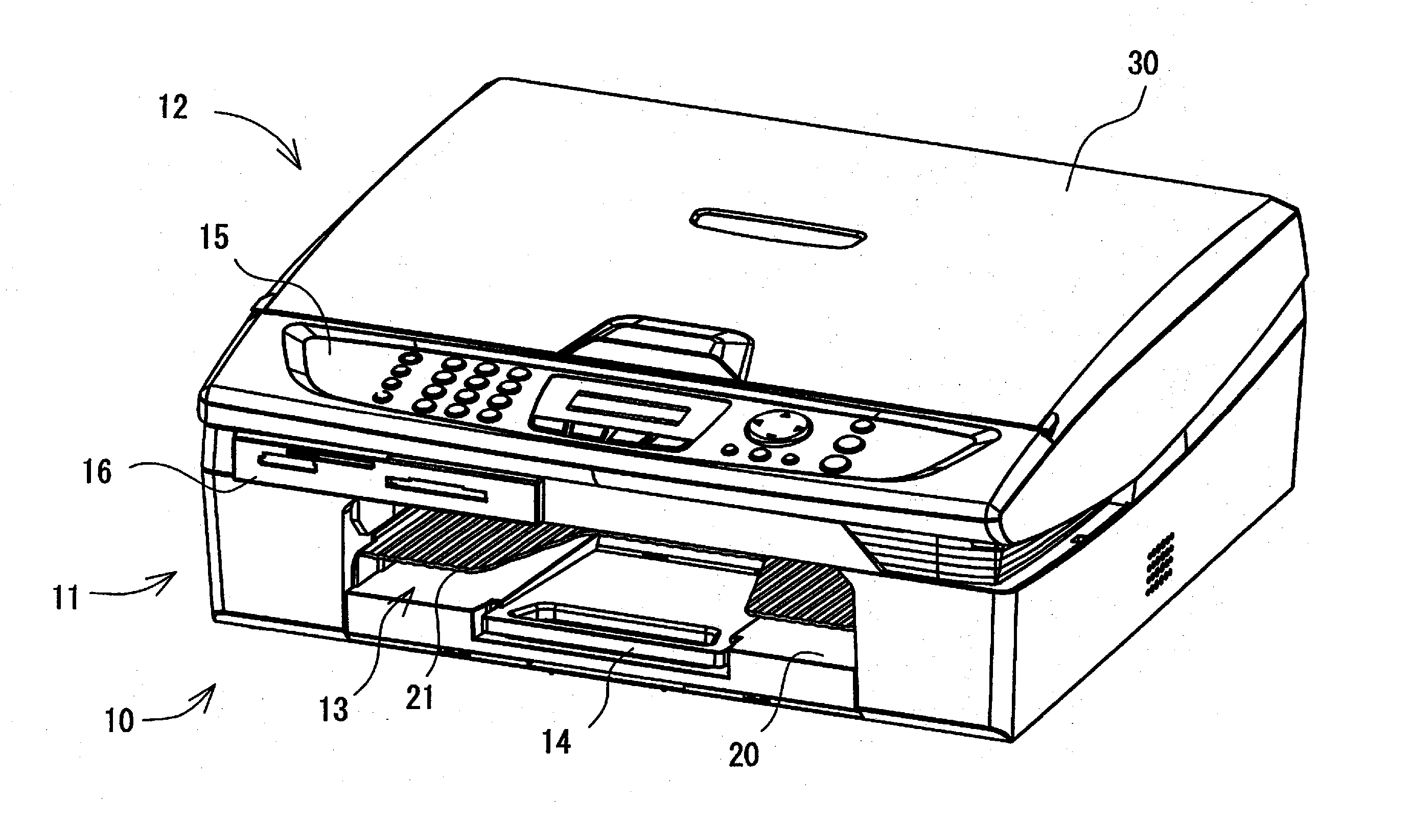
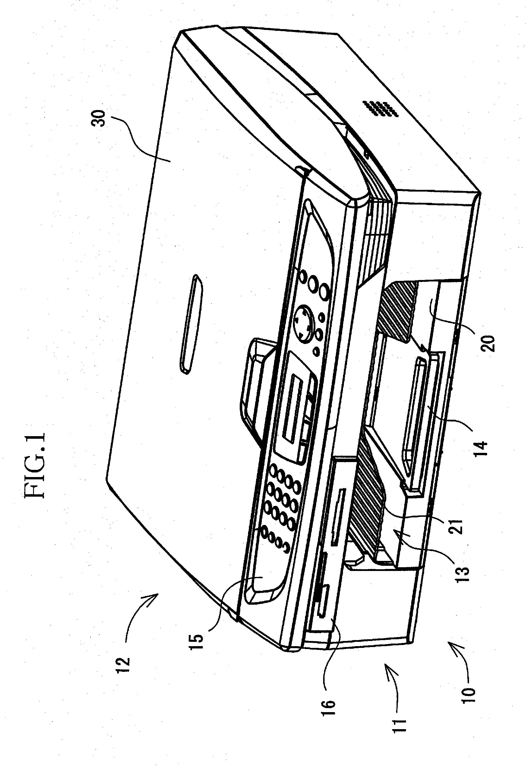
[0033] Hereinafter, there will be described preferred embodiments of the present invention by reference to the drawings. FIG. 1 shows an appearance of a “multi-function device (MFD)”10 as one embodiment of the present invention.

[0034] The MFD 10 has a printer function, a scanner function, and a copier function, and includes a printer portion 11 provided in a lower portion thereof, and a scanner portion 12 provided in an upper portion thereof that is integral with the lower portion. In the present embodiment, the printer portion 11 corresponds to an image recording apparatus to which the present invention is applied. The functions other than the printer function may be omitted, that is, the scanner portion 12 may be omitted. Thus, the present invention may be applied to a single-function printer that has only the printer function and does not have the scanner or copier function. Alternatively, the present invention may be applied to an MFD that additionally employs a communication p...


PUM


Abstract

A supporting apparatus for supporting a movable member such that the movable member is movable along a predetermined path. The apparatus includes a main frame which defines a reference plane parallel to the predetermined path; at least one base member which is supported by the main frame and which supports the movable member such that the movable member is movable on the at least one base member along the predetermined path; at least one positioning device which positions the at least one base member relative to the main frame in at least one first direction parallel to the reference plane and a second direction perpendicular to the reference plane, such that the at least one base member is permitted to be displaced relative to the main frame in a third direction opposite to the second direction; and at least one biasing device which biases the at least one base member toward the main frame in at least the second direction.

Description

[0001] The present application is based on Japanese Patent Application No. 2005-281247 filed on Sep. 28, 2005, the contents of which are incorporated herein by reference. BACKGROUND OF THE INVENTION [0002] 1. Field of the Invention [0003] The present invention relates to an image recording apparatus and, in particular, to a construction of a frame assembly as a supporting apparatus. [0004] 2. Discussion of Related Art [0005]FIG. 13 illustratively shows an image recording portion of a conventional ink-jet recording device. The conventional ink-jet recording device includes a platen 1 on which a recording sheet is placed; and an ink-jet recording head 2 that is reciprocated, along the platen 1, in a main scanning direction (i.e., a direction perpendicular to the drawing of FIG. 13) while ejecting droplets of ink toward the recording sheet so as to record a desired image thereon. Therefore, recording a clear image needs to position accurately the platen 1 and the recording head 2 relat...

Claims


Application Information

Patent Timeline
IPC IPC(8): G03G21/16G03G15/01
CPCB41J2/175B41J29/02B41J19/20B41J2/1752
Inventor UEDA, KIYOSHI
Owner BROTHER KOGYO KK
Why Eureka
Try Eureka