

Image pickup apparatus and image processing method
a technology of image pickup and image processing, which is applied in the direction of color television details, color signal processing circuits, television systems, etc., can solve the problems of unnatural image picked up in the situation as a whole, unnatural combined image depending on the imaging scene, and narrow image dynamic range, so as to achieve the effect of broad dynamic range, and less discrepancy in white balan
- Summary
- Abstract
- Description
- Claims
- Application Information
AI Technical Summary
Benefits of technology
Problems solved by technology
Method used
Image


Examples
first embodiment
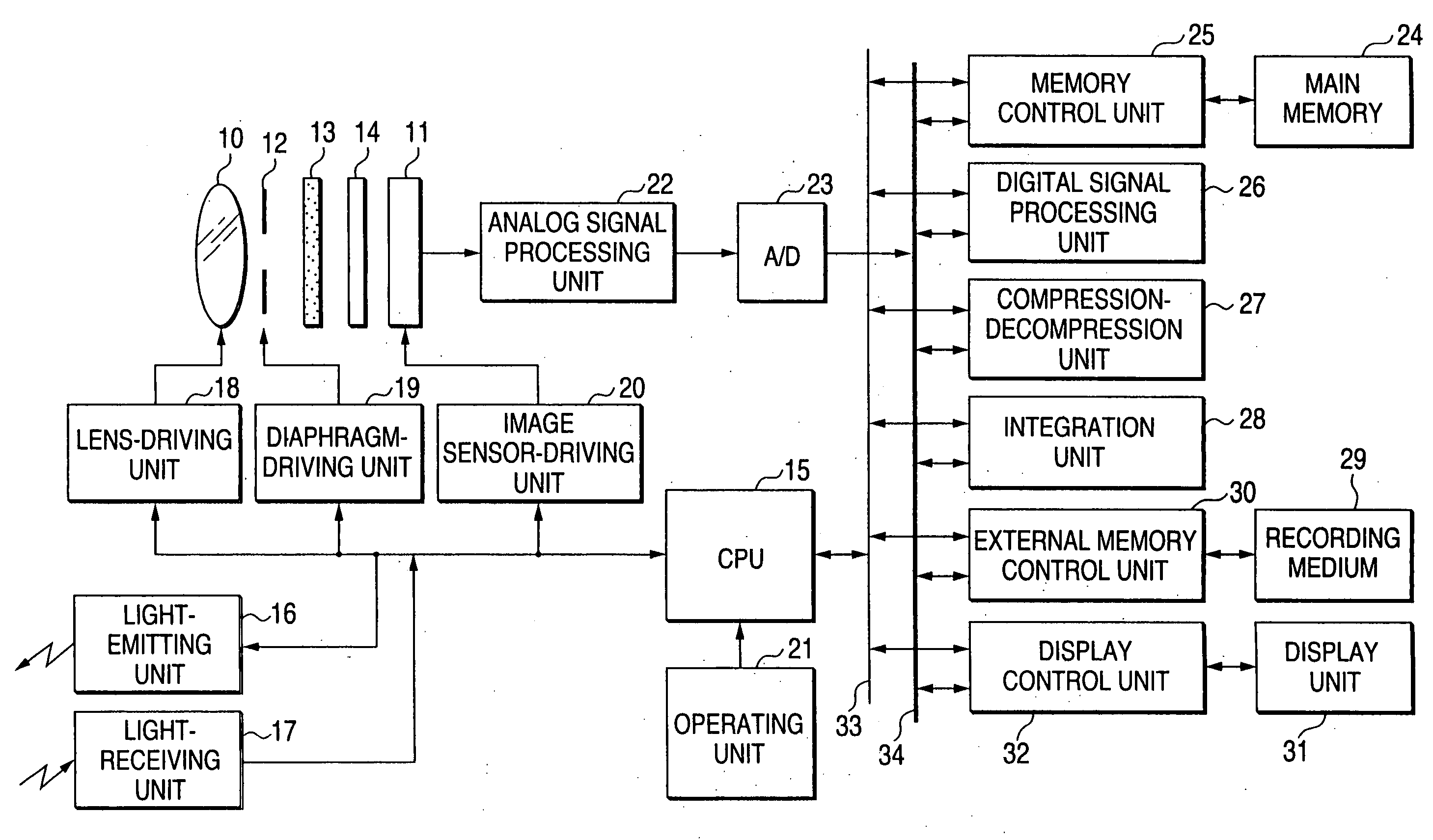
[0055]FIG. 1 is a block diagram of a digital still camera of first embodiment according to the invention. In the first embodiment, the digital still camera is explained for an example, while it is applicable to other types of an image pickup apparatus such as digital video cameras. An image combination operation in the embodiment is performed by software in a digital signal processing unit 26 to be described later, while the image combination operation can be also performed by a hardware circuit.
[0056] The digital still camera shown in FIG. 1 has an imaging lens 10, a solid-state image sensor 11, a lens diaphragm 12 that is positioned between the imaging lens 10 and a solid-state image sensor 11, an infrared-cut filter 13 and an optical low pass filter 14. A CPU 15, which controls the entire digital still camera, controls a light-emitting unit 16 and a light-receiving unit 17 both for photoflash, adjusts a lens-driving unit 18 to regulate the position of the imaging lens 10 to the ...
second embodiment
[0091] Configuration of a digital still camera according to second embodiment is same as that of a digital still camera according to the first embodiment shown in FIG. 1, except a digital signal processing unit. Therefore, a digital signal processing unit of the embodiment is denoted by “26a” in FIG. 6 and “26b” in FIG. 7.
[0092]FIG. 6 is a detailed block diagram of the digital signal processing unit 26a. This digital signal processing unit 26a may be constructed in the form of a hardware circuit or software. In the embodiment, the digital signal processing unit 26a will be described for the case where a low sensitivity image picked up with a high shutter speed (This image is also called “low output image”, since the output from each pixel is low.) and a high sensitivity image sequentially picked up with a low shutter speed (This image is also called “high output image”, since the output from each pixel is higher than the data of the low output image.) are combined.
[0093] The digit...
third embodiment
[0112] In third embodiment, descriptions will be given to the cases where the invention is applied to a digital still camera.
[0113] As shown in FIG. 8, a digital camera 100 as the embodiment has an optical lens 112, a diaphragm 114 which regulates the amount of light transmitting the optical lens 112, a shutter 116 which regulates the light-passing period, a CCD (Charge-Coupled Device) 118 as the image sensor which picks up a scene with high sensitivity and low sensitivity photoreceptors based on the impinging light, which representing the scene, transmitted the optical lens 112, the diaphragm 114 and the shutter 116 to output R, G and B three-color analog image signals.
[0114] The CCD 118 are, in the order, connected to an analog signal processing unit 120 which executes pre-determined analog signal processing on the high sensitivity and low sensitivity signals inputted by the CCD 118, and an analog / digital converter (hereafter, called “A / D converter”) 122 which converts the high ...
PUM
 Abstract
Description
Claims
Application Information