Brush apparatus for rotary electric machine

a technology of rotary electric machines and brushes, which is applied in the direction of electrical apparatus, dynamo-electric machines, current collectors, etc., can solve the problems of undesired power generation in the alternator, the insufficient contact of the brush apparatus, and the failure of the brush apparatus to achieve sufficient contact, so as to prevent the failure of power generation or rotational force generation at an early time, reduce the volume of solder penetrating into the brush wire, and maintain the flexibility or elasticity

Inactive Publication Date: 2007-04-12
DENSO CORP
View PDF6 Cites 7 Cited by
  • Summary
  • Abstract
  • Description
  • Claims
  • Application Information

AI Technical Summary

Benefits of technology

[0011] With this configuration of the brush apparatus, because the ratio of the inner diameter D1 of the connecting hole to the outer diameter D2 of the brush wire satisfies 1.3≦D1/D2<1.5, an open space between the brush wire and the connecting hole is adequately reduced as compared with the prior art wherein the inner diameter of a hole is set to be 1.5 or more times larger than an outer diameter of a wire inserted into the hole. Therefore, a volume of solder penetrating i

Problems solved by technology

However, because the inner diameter of the hole is 1.5 or more times larger than the outer diameter of the wire, a clearance or opening between the wire and the terminal in the hole becomes too large to adequately solder the wire and terminal together.
As a result, a pressing force of the brush body onto the slip ring is lowered, and

Method used


Image

  • Brush apparatus for rotary electric machine
  • Brush apparatus for rotary electric machine
  • Brush apparatus for rotary electric machine

Examples


embodiment

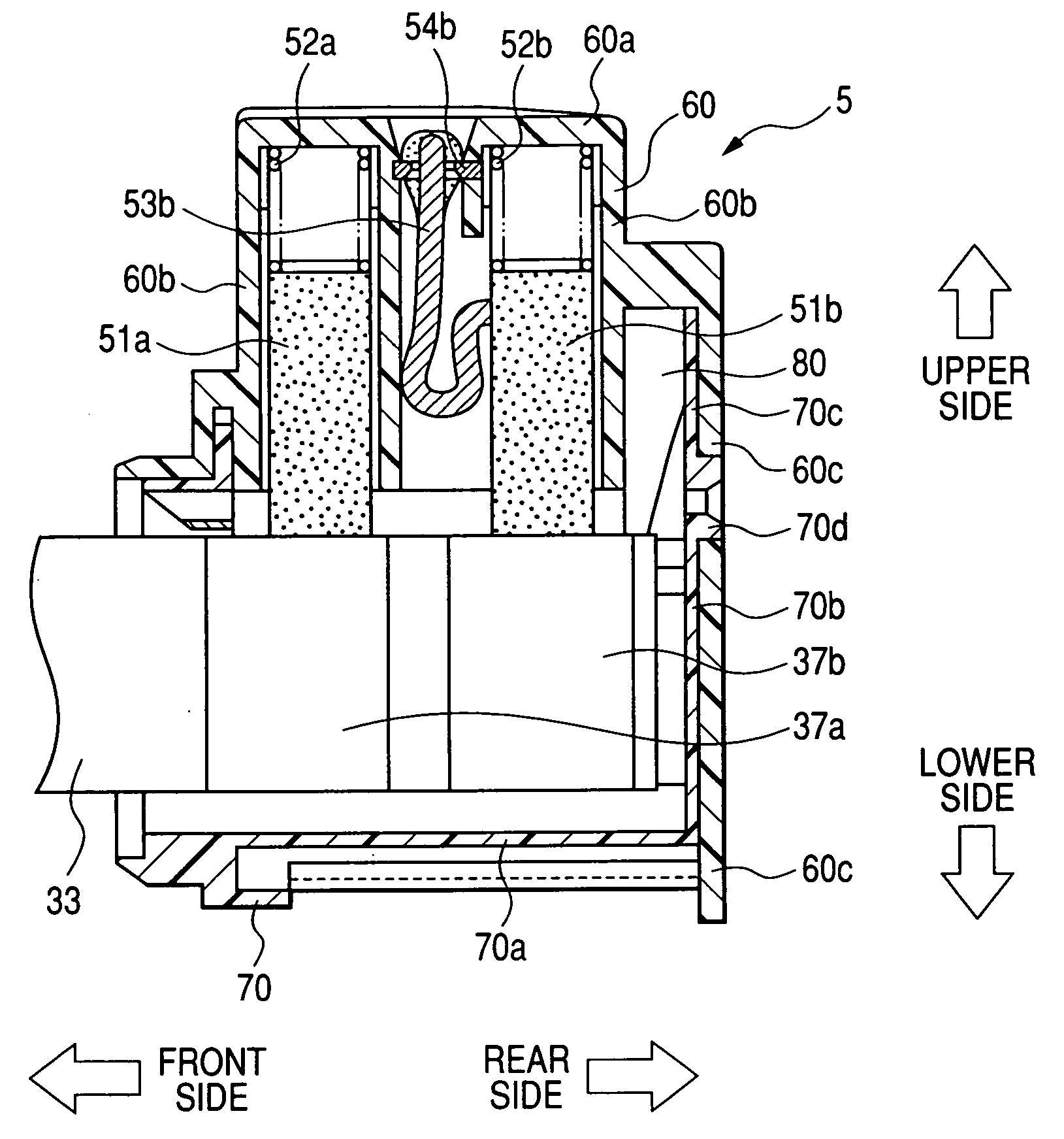
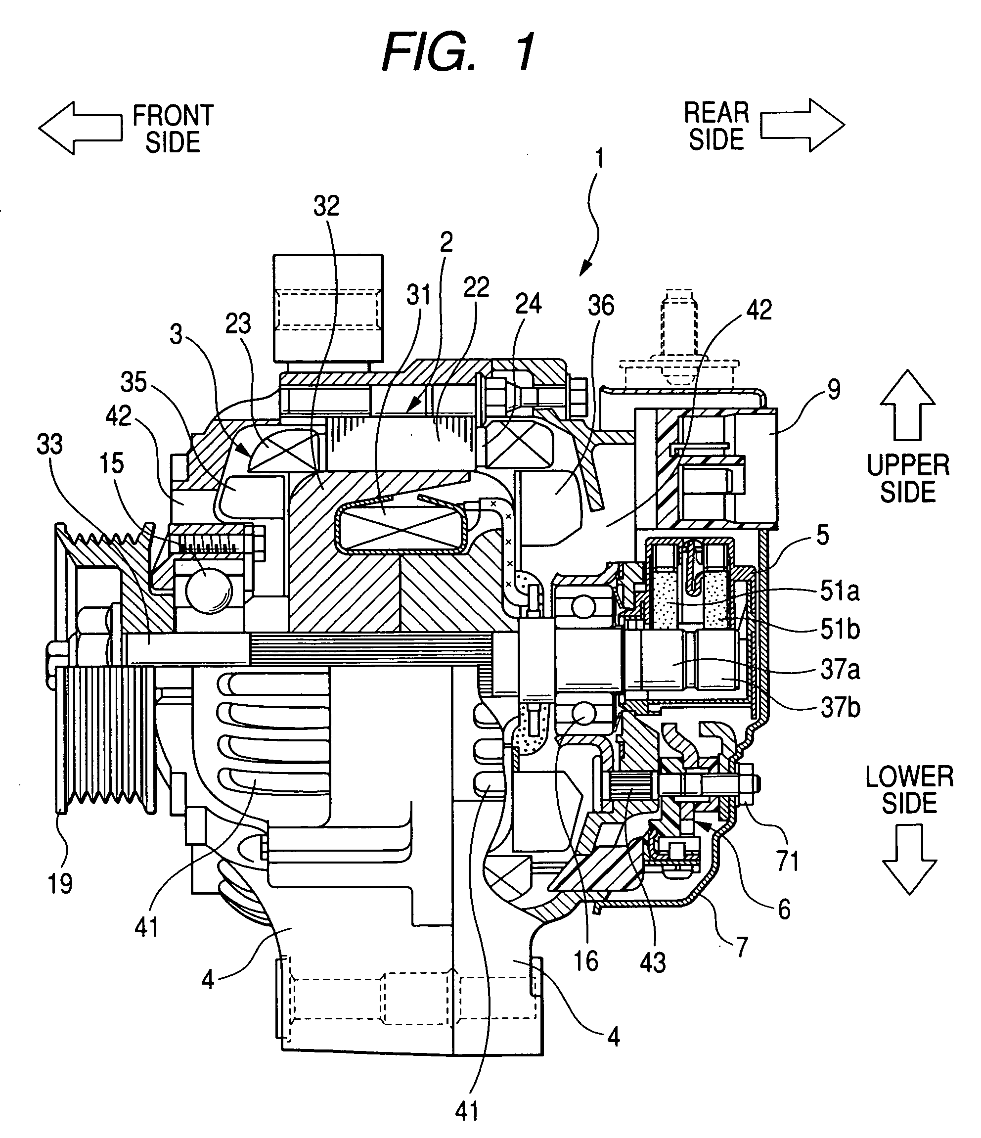
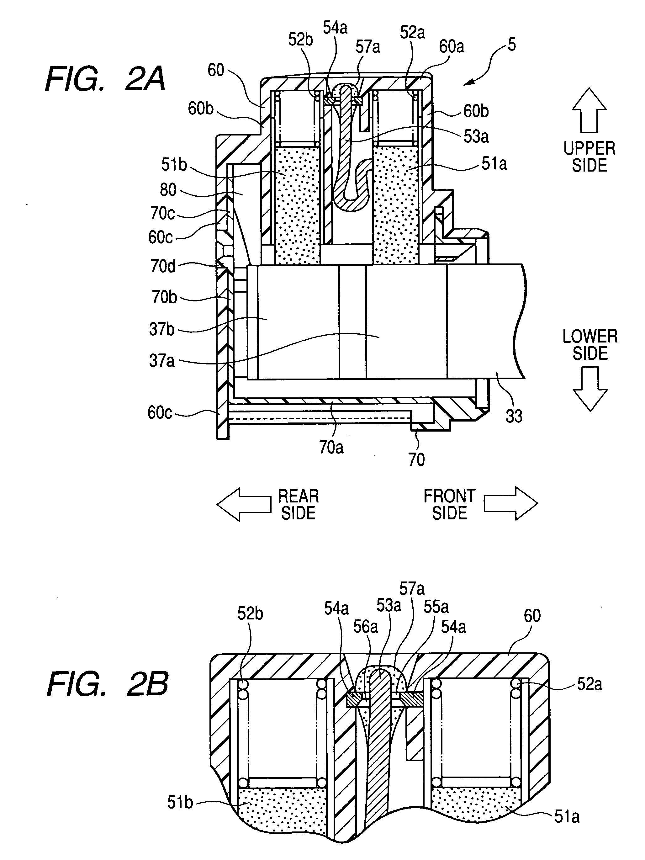
[0023]FIG. 1 is a longitudinal sectional view of an alternator for a vehicle representing a rotary electric machine according to an embodiment of the present invention. As shown in FIG. 1, an alternator 1 for a vehicle has a rotor 3, a stator 2 being disposed so as to surround the rotor 3 at a predetermined clearance and generating electric power based on an electro-magnetic effect caused between the rotor 3 and stator 2, a frame 4 surrounding the rotor 3 and stator 2, a rectifier 6 rectifying a three-phase alternating voltage generated in the stator 2 to produce electric power of a direct current, a brush apparatus 5 supplying a portion of the direct current produced in the rectifier 6 to the rotor 3 as an exciting current, an integrated circuit (IC) regulator 9 adjusting a direct current voltage produced in the rectifier 6 by controlling the exciting current supplied to rotor 3, and a rear cover 7 with which electric parts such as the rectifier 6, the brush apparatus 5 and the IC ...


PUM


Abstract

A brush apparatus for a rotary electric machine has a brush body contacting with a slip ring of a rotor, a spring pressing the brush body on the slip ring, a brush wire connected with the brush body, and a brush terminal having a connecting hole. A ratio of an inner diameter of the hole to an outer diameter of the wire is set to be equal to or higher than 1.3 and to be lower than 1.5. The brush wire is inserted into the hole of the brush terminal, and the brush wire and the terminal are soldered together so as to electrically connect a field winding of the rotor with a rectifier through the brush apparatus.

Description

CROSS-REFERENCE TO RELATED APPLICATION [0001] This application is based upon and claims the benefit of priority of the prior Japanese Patent Application 2005-294468 filed on Oct. 7, 2005, and the prior Japanese Patent Application 2006-176714 filed on Jun. 27, 2006 so that the contents of which are incorporated herein by reference. BACKGROUND OF THE INVENTION [0002] 1. Field of the Invention [0003] The present invention generally relates to a brush apparatus which slides on a slip ring of a rotor during rotation of the rotor to supply an exciting current to a field winding of the rotor in a rotary electric machine such as an alternator used for a vehicle. [0004] 2. Description of Related Art [0005] A brush apparatus is mounted in an alternator for a vehicle and slides on a slip ring of a rotor during rotation of the rotor to supply an exciting current to a field winding of the rotor. The alternator generates a three-phase alternating current in response to the exciting current. [0006...

Claims


Application Information

Patent Timeline
IPC IPC(8): H01R39/38
CPCH01R39/36H01R39/383
Inventor YOSHIMURA, HIROKI
Owner DENSO CORP
Why Eureka
Try Eureka