Image forming device and image forming method

a technology of image forming and forming method, which is applied in the direction of digital output to print units, instruments, digitally marking record carriers, etc., can solve the problems of printing images in a disordered manner on the front and back of the sheet, the device including binding processing cannot be applied in many cases, and the situation is not convenien

Inactive Publication Date: 2007-04-26
KYOCERA DOCUMENT SOLUTIONS INC
View PDF4 Cites 4 Cited by
  • Summary
  • Abstract
  • Description
  • Claims
  • Application Information

AI Technical Summary

Benefits of technology

[0016] The invention in Claim 3 makes it possible to align sheets and to stack sheets in page number order, when sheets are stacked, because sheets are printed with one document image page on the back of a sheet of two document pages and cut down the center line.

Problems solved by technology

However, these technologies relate to devices including binding processing and cannot be applied in many cases where binding processing is not necessary.
Therefore, when the printed sheets are stacked, the sheets are not aligned and this situation is not convenient.
Also, with the former image forming method, because the position of the binding margins or binding holes of the printed sheets are different for each page as shown in FIG. 14, a problem is that when the sheets are cut and stacked, the print images are printed in a disordered manner on the fronts and backs of the sheets.
In the image forming method in the Patent Document 2, a problem is that the binding margin is not positioned within the sheet, as shown in FIG. 15.
When adding the positioning of the binding margin to printing with the latter technique, a problem is that the position of the binding margin varies from page to page because the cutting edge of the paper cut along the center line thereof appears on the right side or the left side (FIG. 16).

Method used


Image

  • Image forming device and image forming method
  • Image forming device and image forming method
  • Image forming device and image forming method

Examples


first embodiment

[0035] An image forming device according to the present invention is an image forming device for performing image processing such as reduction, enlargement, layout, and the like for image data read from a scanner or a host computer connected on a network; examples include copiers, printers, facsimile machines, multi-function machines, or the like.

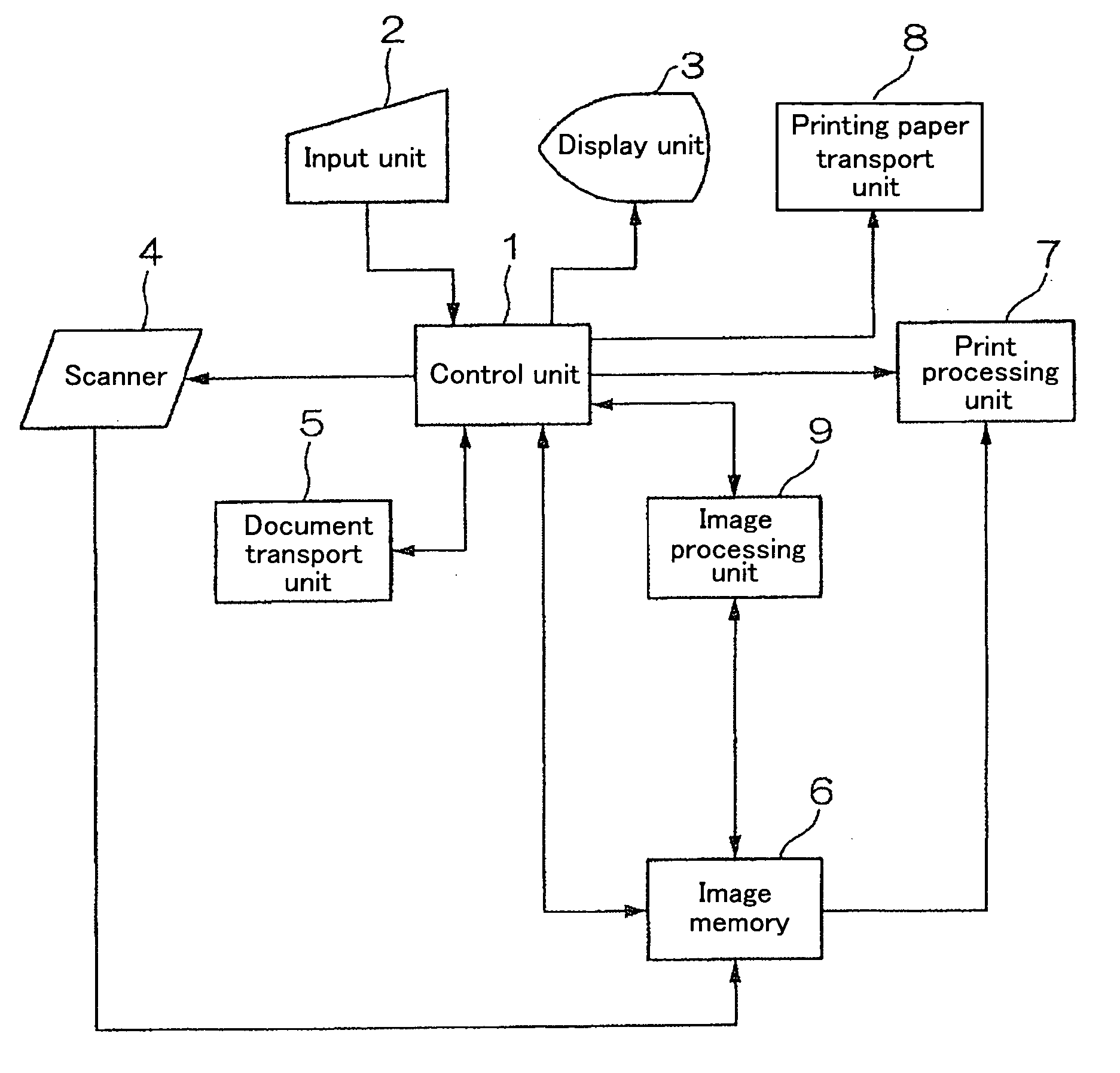
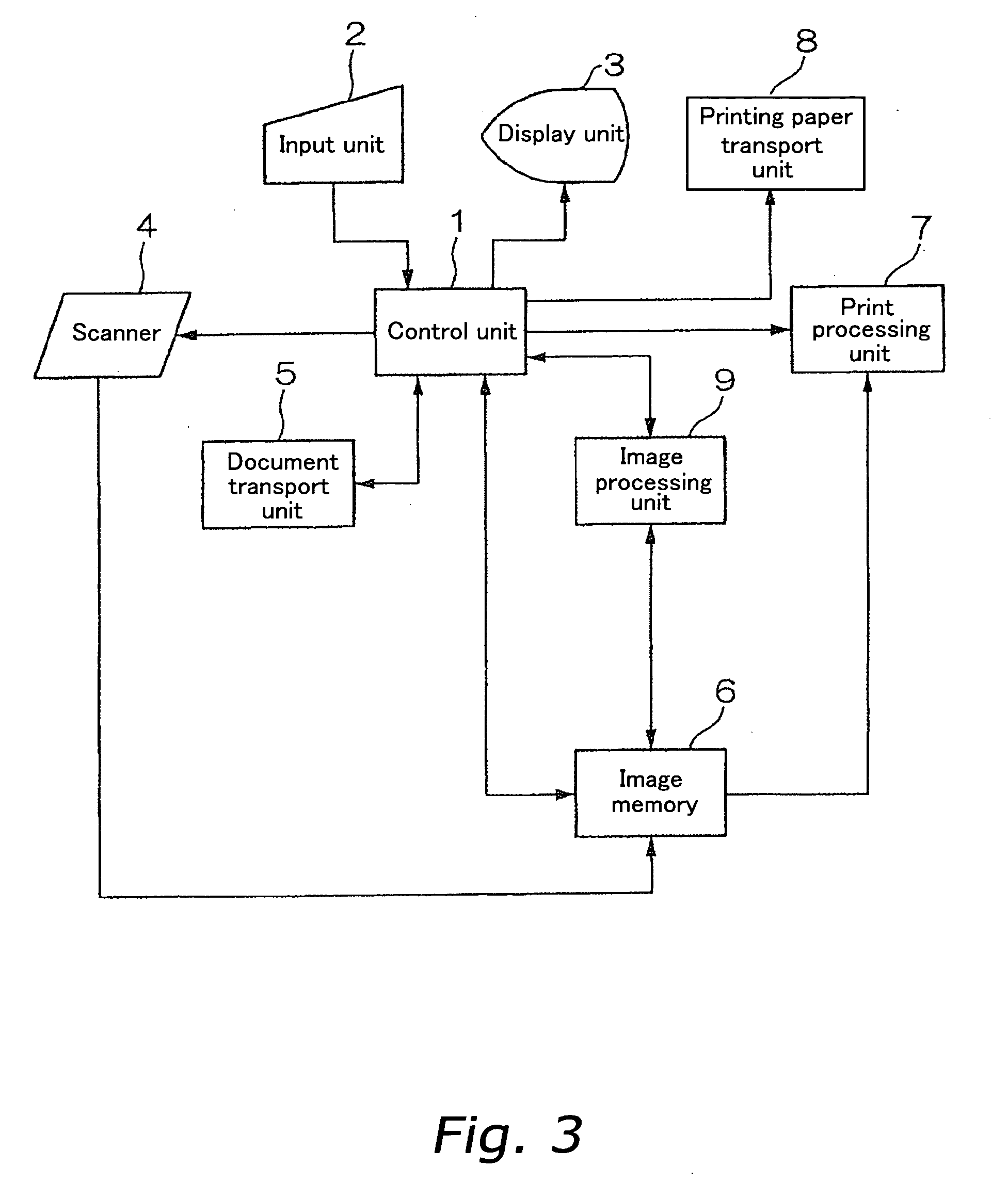
[0036] An image forming device according to the first embodiment, in a copier according to the present invention, is described below with reference to the drawings. FIG. 3 is a block diagram showing the constitution of this embodiment. The reference 1 is a control unit for administering and controlling the processing operations of the image forming device. The reference 2 is an input unit comprising a touch panel, function keys, numeric key pad, keyboard and the like. The reference 3 is a display unit comprising a liquid crystal display or the like. The reference 4 is a scanner comprising a document loader for positioning a multi-page docu...

second embodiment

[0047] An image forming device according to the present invention is an image forming device for performing image processing such as reduction, enlargement, layout, and the like for image data read from a scanner or a host computer connected on a network; examples include copiers, printers, facsimile machines, multi-function machines, or the like.

[0048] An image forming device according to the second embodiment, in a copier according to the present invention, is described below with reference to the drawings. FIG. 11 is a block diagram showing the constitution of this embodiment. The reference 51 is a control unit for administering and controlling the processing operations of the image forming device. The reference 52 is an input unit comprising a touch panel, function keys, numeric key pad, keyboard, or the like. The reference 53 is a display unit comprising a liquid crystal display or the like. The reference 54 is a scanner comprising a document loader for positioning a multi-pag...


PUM


Abstract

A document input from a scanner is used as input image data and is stored in image memory in page number order. A control unit prints the input image data and receives instruction data showing the cutting edge when cutting on the center line of the printing paper from the input unit. The control unit stores the addresses at which the input image data are stored in an array A; the image processing unit sorts the addresses stored in the first or second half of the array A, based on instruction data shown by the instruction data discussed above, in descending order by page number. The image processing unit alternates and stores in an array B addresses stored in the first or second half of the sorted array A, and in the first or second half of the unsorted array A. The print processing unit prints the input image data, in the order stored in the array B, on both sides of printing paper, and attains printing results as shown in FIG. 1.

Description

FIELD OF THE INVENTION [0001] The present invention relates to an image forming device such as a copier, printer, a multi-function machine having these fictions, or the like. BACKGROUND INFORMATION [0002] Before now, with the purpose of improving printing efficiency for image forming devices such as copiers, printers, or the like, a general usage was to print two pages on one sheet of printing paper, of the size of two document pages, and cut along the center line of the printed sheets. A method is known for forming binding holes or binding margins on the sheets, in the case where the printed sheets are cut along the center line of the sheets and stacked, after which binding processing is performed. In devices which do not perform binding processing, an image forming method is known which can stack the pages in ascending order if the printed sheets are stacked in cutting order. [0003] However, these technologies relate to devices including binding processing and cannot be applied in...

Claims


Application Information

Patent Timeline
Patent Type & Authority Applications(United States)
IPC IPC(8): G06F3/12
CPCG06F17/211H04N1/32358H04N1/32464H04N2201/0091G06F40/103
Inventor SAKEMI, RYOICHI
Owner KYOCERA DOCUMENT SOLUTIONS INC
Why Eureka
Try Eureka