Scroll machine

a compressor and rolling machine technology, applied in the direction of machines/engines, rotary/oscillating piston pump components, liquid fuel engines, etc., can solve the problems of strong tendency for the backflow of compressed gas, noise or rumble, objectionable and undesirable, etc., to reduce or eliminate the problem of reverse rotation, increase and maximize the performance of the compressor

Inactive Publication Date: 2007-05-17
PEYTON JESSE
View PDF45 Cites 35 Cited by
  • Summary
  • Abstract
  • Description
  • Claims
  • Application Information

AI Technical Summary

Benefits of technology

[0004] Because scroll compressors depend upon successive chambers for suction, compression, and discharge processes, suction and discharge valves in general are not required. However, the performance of the compressor can be increased with the incorporation of a discharge valve. One of the factors that will determine the level of increased performance is the reduction of what is called recompression volume. The recompression volume is the volume of the discharge chamber and the discharge port of the compressor when the discharge chamber is at its smallest volume. The minimization of this recompression volume will result in a maximizing of the performance of the compressor. In addition, when such compressors are shut down, either intentionally as a result of the demand being satisfied, or unintentionally as a result of a power interruption, there is a strong tendency for the backflow of compressed gas from the discharge chamber and to a lesser degree for the gas in the pressurized chambers to effect a reverse orbital movement of the orbiting scroll member and its associated drive shaft. This reverse movement often generates noise or rumble, which may be considered objectionable and undesirable. Further, in machines employing a single phase drive motor, it is possible for the compressor to begin running in the reverse direction should a momentary power interruption be experienced. This reverse operation may result in overheating of the compressor and / or other inconveniences to the utilization of the system. Additionally, in some situations, such as a blocked condenser fan, it is possible for the discharge pressure to increase sufficiently to stall the drive motor and effect a reverse rotation thereof. As the orbiting scroll orbits in the reverse direction, the discharge pressure will decrease to a point where the motor again is able to overcome this pressure head and orbit the scroll member in the forward direction. However, the discharge pressure will again increase to a point where the drive motor is stalled and the cycle is repeated. Such cycling is undesirable in that it is self-perpetuating. The incorporation of a discharge valve can reduce or eliminate these reverse rotation problems.

Problems solved by technology

In addition, when such compressors are shut down, either intentionally as a result of the demand being satisfied, or unintentionally as a result of a power interruption, there is a strong tendency for the backflow of compressed gas from the discharge chamber and to a lesser degree for the gas in the pressurized chambers to effect a reverse orbital movement of the orbiting scroll member and its associated drive shaft.
This reverse movement often generates noise or rumble, which may be considered objectionable and undesirable.
This reverse operation may result in overheating of the compressor and / or other inconveniences to the utilization of the system.
However, the discharge pressure will again increase to a point where the drive motor is stalled and the cycle is repeated.
Such cycling is undesirable in that it is self-perpetuating.

Method used


Image

  • Scroll machine
  • Scroll machine
  • Scroll machine

Examples


Embodiment Construction

[0014] The following description is merely exemplary in nature and is not intended to limit the present disclosure, application, or uses.

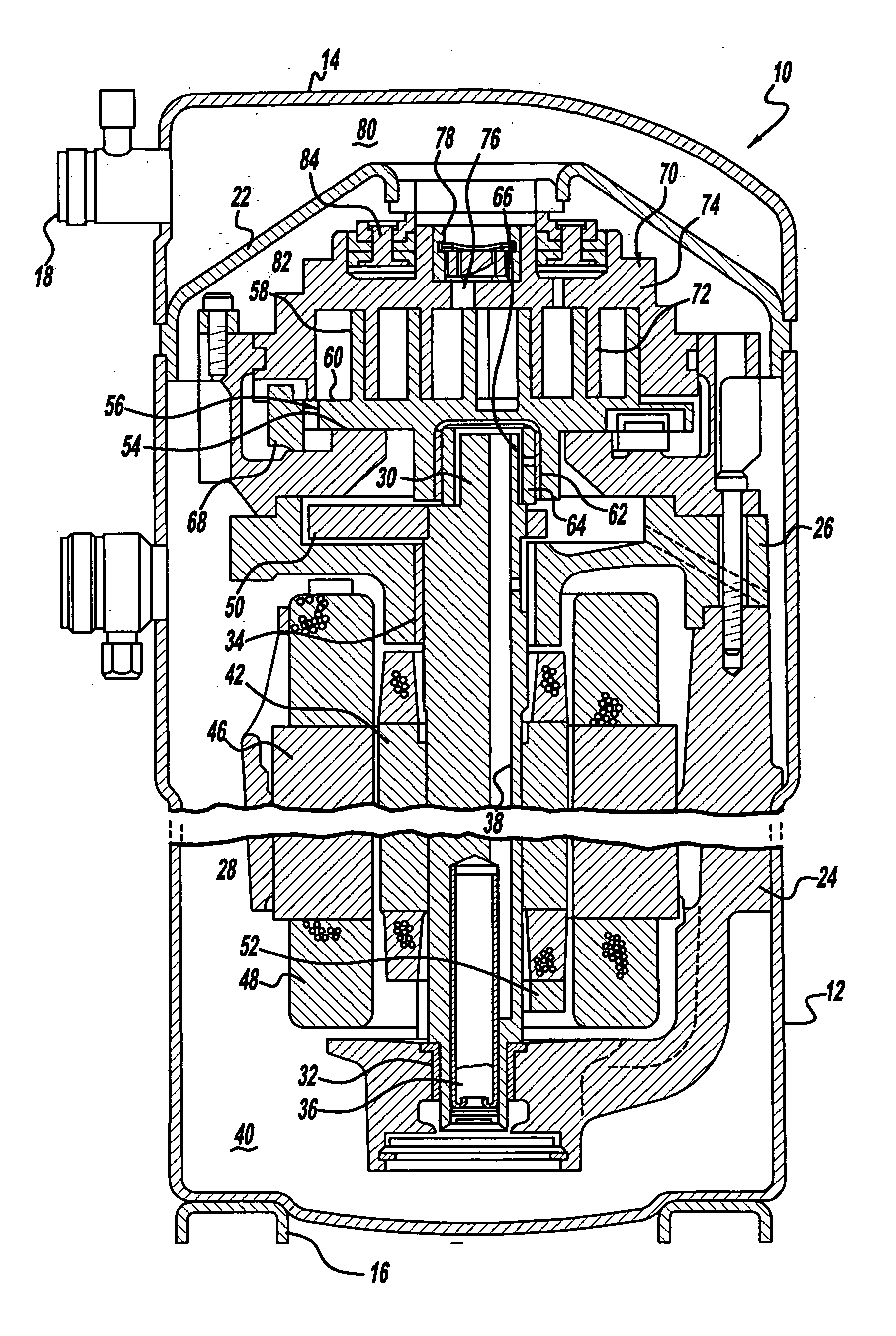
[0015] Referring now to the drawings in which like reference numerals designate like or corresponding parts throughout the several views, there is shown. in FIG. 1 a scroll compressor that incorporates a retention system for a discharge valving system in accordance with the present disclosure and which is designated generally by reference numeral 10. Compressor 10 comprises a generally cylindrical hermetic shell 12 having welded at the upper end thereof a cap 14 and at the lower end thereof a base 16 having a plurality of mounting feet (not shown) integrally formed therewith. Cap 14 is provided with a refrigerant discharge fitting 18. Other major elements affixed to the shell include a transversely extending partition 22 that is welded about its periphery at the same point that cap 14 is welded to shell 12, a lower bearing housing 24 that is suita...


PUM


Abstract

A scroll machine includes a shell defining a discharge chamber, a first scroll member having a first spiral wrap projecting outwardly from a first end cap, a second scroll member having a second spiral wrap projecting outwardly from a second end cap intermeshed with the first spiral wrap, and a drive member causing the scroll members to orbit relative to one another. The spiral wraps create pockets of progressively changing volume between a suction pressure zone and a discharge pressure zone with the discharge pressure zone being in communication with the discharge chamber. A discharge valve assembly is disposed between the discharge pressure zone and the discharge chamber and is movable relative to the first scroll member. The discharge valve assembly includes a valve plate movable between a first open state and a closed state.

Description

CROSS-REFERENCE TO RELATED APPLICATIONS [0001] This application is a continuation of U.S. patent application Ser. No. 10 / 671,049 filed on Sep. 25, 2003. The disclosure of the above application is incorporated herein by reference.FIELD [0002] The present disclosure relates to rotary compressors. More particularly the present disclosure relates to a direct discharge valve system that is utilized in a compressor. BACKGROUND AND SUMMARY [0003] Scroll machines are becoming more and more popular for use as compressors in both refrigeration as well as air conditioning and heat pump applications due primarily to their capability for extremely efficient operation. Generally, these machines incorporate a pair of intermeshed spiral wraps, one of which is caused to orbit relative to the other so as to define one or more moving chambers that progressively decrease in size as they travel from an outer suction port towards a center discharge port. An electric motor is normally provided that operat...

Claims


Application Information

Patent Timeline
Patent Type & Authority Applications(United States)
IPC IPC(8): F01C1/02F01C1/063F03C2/00F04C18/02F04C23/00F04C29/12
CPCF04C18/0215F04C23/008F04C29/128F04C2270/58F04C18/02
Inventor PEYTON, JESSE
Owner PEYTON JESSE
Why Eureka
Try Eureka