Picture encoding method and apparatus and picture decoding method and apparatus

a picture encoding and picture technology, applied in the field of picture encoding methods and apparatuses, can solve the problems of affecting the encoding efficiency of the picture, the decoding quality is noticeably deteriorating, and the predictive error is added to the residual error, so as to achieve the effect of quick recovery from an error and high encoding efficiency

Inactive Publication Date: 2007-07-05
NAGAI TAKESHI +4
View PDF12 Cites 0 Cited by
  • Summary
  • Abstract
  • Description
  • Claims
  • Application Information

AI Technical Summary

Benefits of technology

[0015] It is an object of the present invention to provide a picture encoding method and apparatus and a picture decoding method and apparatus which can quickly recover from an error even if information is lost by the error, exhibit high encoding efficiency, and need not perform any re-encoding.

Problems solved by technology

First, in a communication path with the possibility of being mixed with errors, such as a radio communication path, performing only encoding will lead to considerable deterioration in decoded picture quality upon occurrence of an error.
When errors occur in signals such as a sync signal, mode information, and motion vector information, in particular, picture quality noticeably deteriorates.
A predictive picture is generated by using the erroneous picture, and the residual error is added to the predictive error.
As a consequence, even if subsequent frames are properly decoded, proper pictures cannot be obtained from the subsequent frames unless information is sent in an encoding mode (INTRA mode) of encoding pictures only within frames without using the differences between the frames or the influence of the error gradually wanes to restore the original pictures.
Subsequently, residual errors are added to wrong pictures.
In this periodic refresh method, however, although an increase in the number of coded bits can be suppressed, a long period of time is required to recover a normal state.
Although this scheme can correct errors that occur randomly, it has difficulty in coping with errors of several hundred bits that consecutively occur in a burst manner.
Even if the scheme can cope with such errors, considerable redundancy occurs.
As described above, according to the conventional picture encoding techniques, loss of information due to an error causes a great deterioration in picture quality.
In addition, a technique such as the periodic refresh method of reconstructing information lost due to an error requires a long period of time to achieve error recovery in consideration of the encoding efficiency.
Shortening the time required for recovery will increase the number of encoded bits to result in a deterioration in encoding efficiency.

Method used


Image

  • Picture encoding method and apparatus and picture decoding method and apparatus
  • Picture encoding method and apparatus and picture decoding method and apparatus
  • Picture encoding method and apparatus and picture decoding method and apparatus

Examples


first embodiment

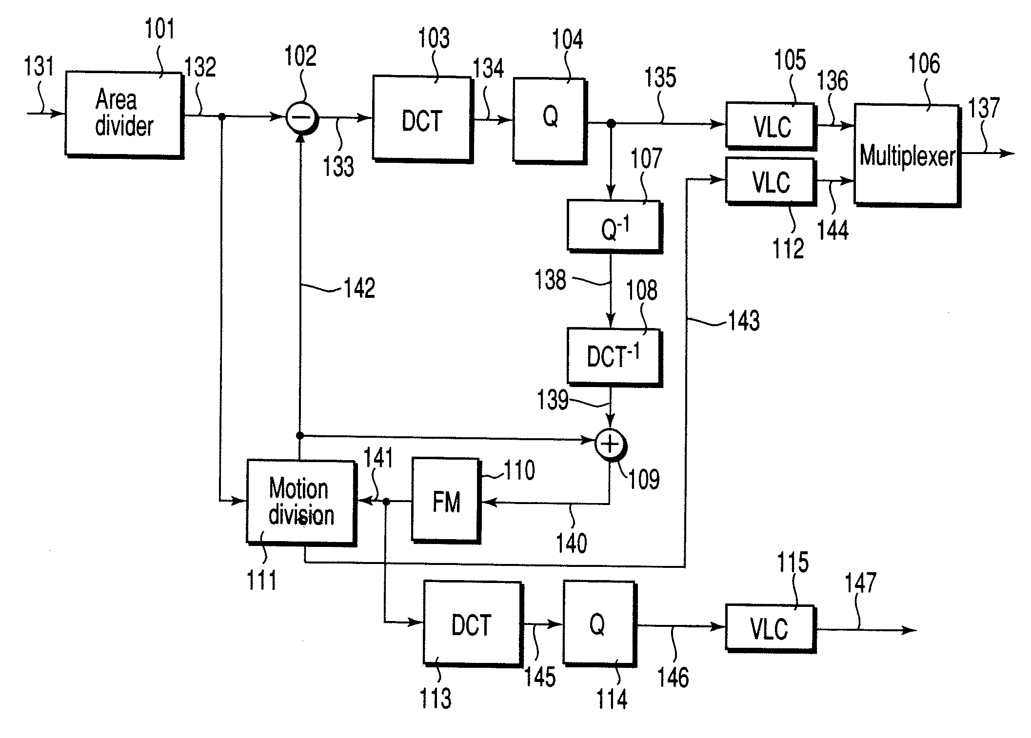
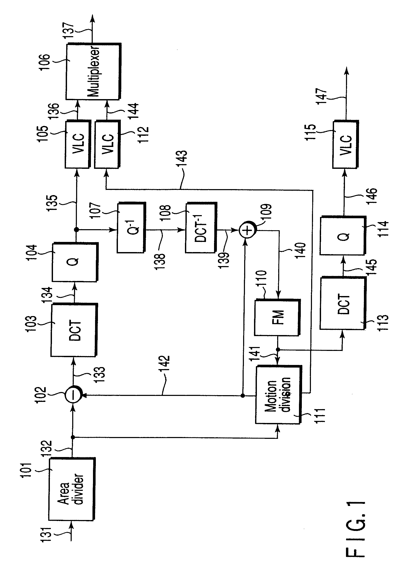
[0037]FIG. 1 shows the basic arrangement of a picture encoding apparatus according to the first embodiment of the present invention.

[0038] An input video signal 131 is divided into a plurality of predetermined areas first by an area divider 101 and then subjected to the following motion compensation adaptive prediction. A motion compensation adaptive predictor 111 detects a motion vector 143 between an input picture signal 132 and a reference picture signal 141 of the previous frame which is stored in a frame memory 110 and has already been encoded and subjected to a local decoding. Motion compensation is performed for the reference picture signal 141 by using this motion vector. This generates a predictive picture signal (the reference picture signal after motion compensation) 142. The motion compensation adaptive predictor 111 selects a suitable prediction mode of the motion compensation prediction mode and the intra encoding (predictive picture signal=0) mode using the input pic...

second embodiment

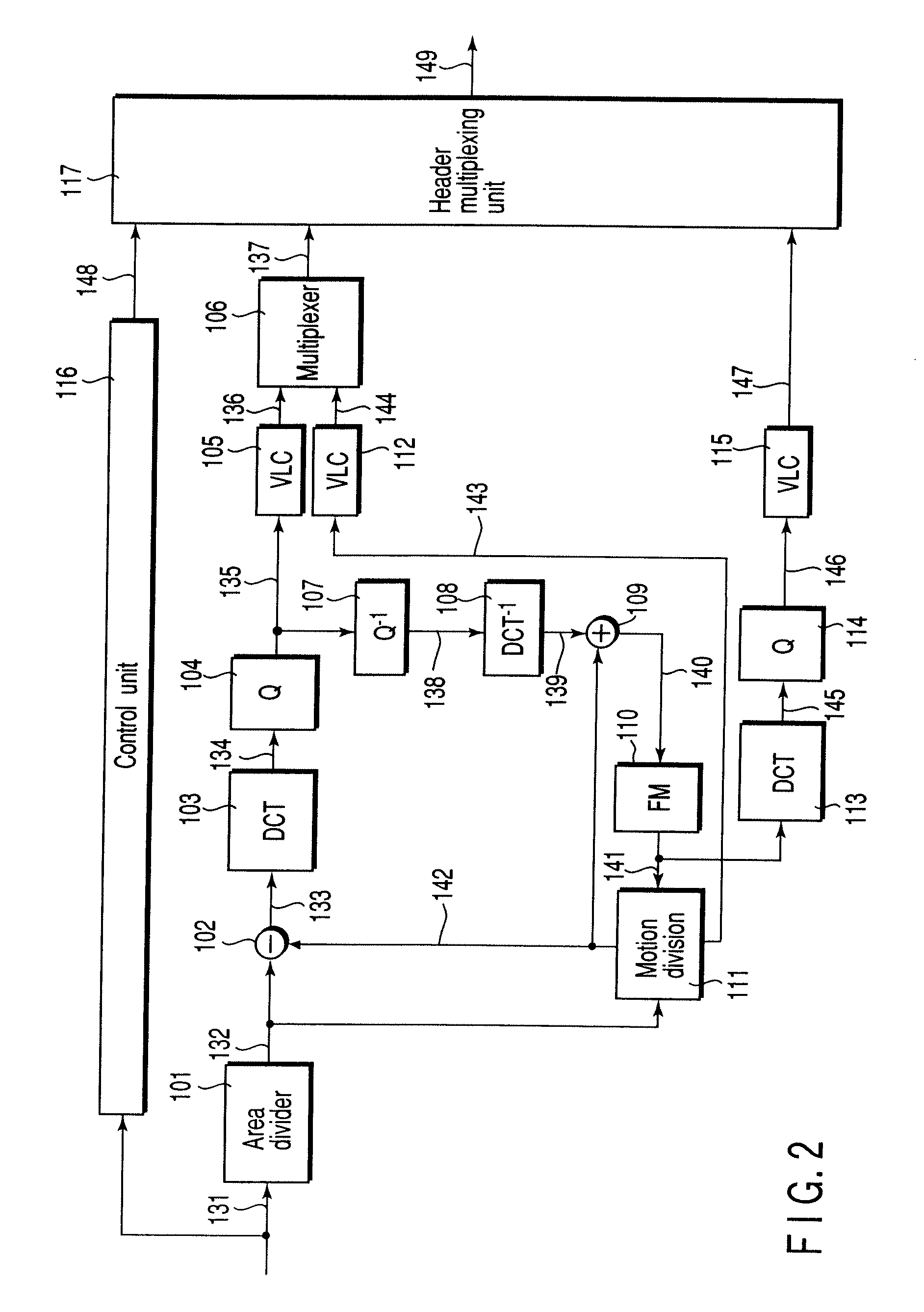
[0061]FIG. 11 shows the arrangement of a picture encoding apparatus according to the second embodiment of the present invention. In the first embodiment, a reference picture code stream is output as a frame different from a video code stream. In the second embodiment, a reference picture code stream is output as additional information for the frames of a video code stream. The same reference numerals as in FIG. 1 denote the same parts in FIG. 11, and only the differences from the picture encoding apparatus according to the first embodiment will be described. In this embodiment, a reference picture code stream 147 is input to a multiplexer 106 to be multiplexed with a quantized and variable-length-encoded DCT coefficient 136 and motion vector code stream 144. The resultant data is then output.

[0062] With this arrangement, a reference picture signal required to encode and decode a specific frame of a video code stream is added to the frame. More specifically, as shown in FIG. 12, the...

third embodiment

[0065]FIG. 14 shows the arrangement of a picture encoding apparatus according to the third embodiment of the present invention. In the first and second embodiments, the reference picture code stream 147 is generated by encoding the reference picture signal stored in the frame memory 110. In the third embodiment, a reference picture code stream 147 is generated by encoding a reference picture signal (predictive picture signal) after motion compensation. In this motion compensation, a reference picture obtained by selecting optimal portions from the reference picture signal stored in a frame memory 110 on a small area basis (mainly on a macroblock basis) is generally stored in the frame memory. For this reason, a reference picture signal 142 after motion compensation is a signal selected from a reference picture signal 141 stored in the frame memory 110 on a macroblock basis.

[0066] Referring to FIG. 14, the reference picture signal 142, which has undergone motion compensation (select...


PUM


Abstract

A picture encoding method includes receiving an input video signal, encoding the video signal using a reference picture signal to generate a video code stream, encoding the reference picture signal to generate a reference picture code stream, and multiplexing the video code stream with the reference picture code stream to generate an output code stream.

Description

CROSS-REFERENCE TO RELATED APPLICATIONS [0001] The present divisional application claims the benefit of priority under 35 U.S.C. §120 to application Ser. No. 10 / 661,697, filed Sep. 15, 2003, which is a Continuation Application of PCT Application No. PCT / JP03 / 00426, filed Jan. 20, 2003, which was not published under PCT Article 21(2) in English; and under 35 U.S.C. § 119 from Japanese applications Nos. 2002-010875, filed on Jan. 18, 2002, and 2003-010135, filed on Jan. 17, 2003, the entire contents of each are hereby incorporated herein by reference.BACKGROUND OF THE INVENTION [0002] 1. Field of the Invention [0003] The present invention relates to a picture encoding method of compression-encoding a picture in a few number of bits and a picture decoding method of playing back a picture by decoding a code stream obtained by compression encoding and, more particularly, to a picture encoding method and apparatus and a picture decoding method and apparatus which can make a recovery from ...

Claims


Application Information

Patent Timeline
Patent Type & Authority Applications(United States)
IPC IPC(8): H04N11/02H04N7/12G06T9/00H04N19/50H03M7/36H04N19/105H04N19/107H04N19/164H04N19/423H04N19/463H04N19/513H04N19/625H04N19/65H04N19/70H04N19/89H04N19/895H04N19/91
CPCH04N19/517H04N19/89H04N19/58H04N19/105H04N19/176H04N19/70H04N19/172H04N19/46H04N19/61H04N19/107H04N19/164H04N19/166H04N19/39H04N19/65H04N19/895
Inventor NAGAI, TAKESHICHUJOH, TAKESHIKOTO, SHINICHIROKIKUCHI, YOSHIHIROASANO, WATARU
Owner NAGAI TAKESHI
Why Eureka
Try Eureka