Backflow prevention device

a technology of backflow and valve body, which is applied in the direction of valve body, functional valve type, transportation and packaging, etc., can solve the problem of backflow and other problems

Inactive Publication Date: 2007-09-06
RAIN BIRD CORP
View PDF87 Cites 17 Cited by
  • Summary
  • Abstract
  • Description
  • Claims
  • Application Information

AI Technical Summary

Problems solved by technology

Backflow is caused by abnormalities in the water distribution system such as backpressure or backsiphonage.
Backsiphonage can occur when the water supply pressure drops, such as when a water main breaks or severe demands are placed on the water supply.
Either condition could lead to backflow, the flow of water from the downstream system back into the water supply.
Backflow is undesirable because it may cause contamination of the potable water supply.

Method used


Image

  • Backflow prevention device
  • Backflow prevention device
  • Backflow prevention device

Examples


Embodiment Construction

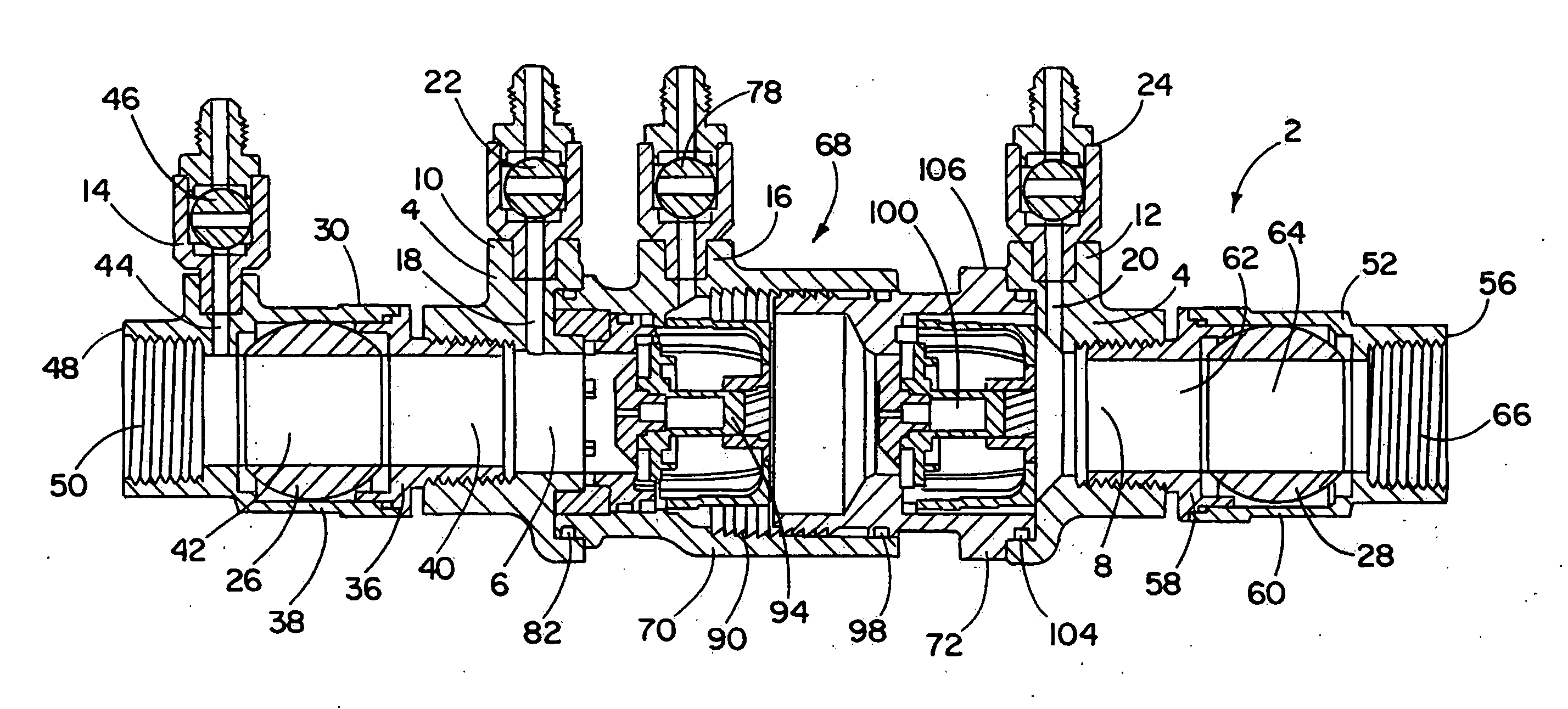
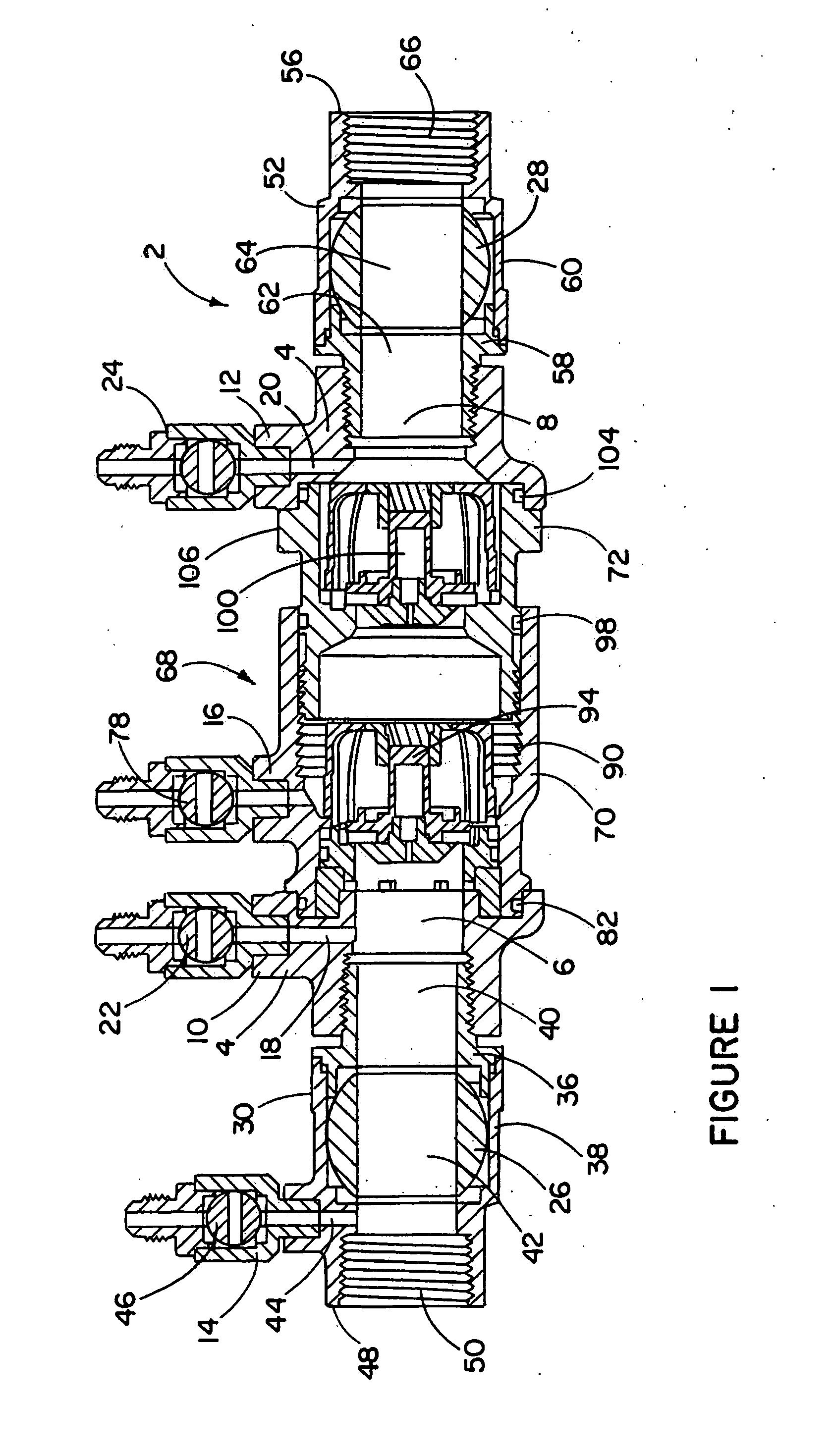
[0024] In FIG. 1, there is illustrated a backflow prevention device 2. A main body 4 provides structural support for the other components and defines fluid flow passages 6, 8 at each end of the main body 4. Test ports 10, 12 are each in fluid communication with one of the fluid flow passages 6, 8 via a test port channel 18, 20. The test ports 10, 12 allow for evaluation of the function of the backflow prevention device 2 in a manner described below. A test port valve 22, 24 is attached to each test port 10, 12.

[0025] An inlet ball valve 26 and an outlet ball valve 28 make it possible to isolate the backflow prevention device 2 from the water system to which it is connected. The inlet ball valve 26 is mounted in a ball valve housing 30 which is mounted to the main body 4, preferably by means of a threaded engagement. The ball valve housing 30 may comprise a mounting portion 36 and a valve containment portion 38, each defining a fluid flow passage 40, 42 respectively. A test port 14 ...


PUM


Abstract

A backflow prevention device includes a main body holding a removable cartridge. The removable cartridge houses two independently acting check valves and, optionally, a relief valve. A first portion of the cartridge may be retracted into a second portion of the cartridge, thereby reducing the overall length of the cartridge and facilitating the removal of the cartridge from the main body without the need to remove the backflow prevention device from a water supply system. The relief valve is contained in a removable cartridge. Each check valve may have a self cleaning plunger bore comprising at least one spiral groove.

Description

CROSS-REFERENCE TO RELATED APPLICATION [0001] This application is a continuation-in-part of co-pending U.S. application Ser. No. 11 / 365,413, filed Mar. 1, 2006. This application hereby incorporates by reference the foregoing related application.FIELD OF THE INVENTION [0002] The present invention generally relates to a backflow prevention device and, in particular, to a removable cartridge housing check valves, a relief valve cartridge, and / or a self cleaning check valve for a backflow prevention device. BACKGROUND OF THE INVENTION [0003] Backflow prevention devices are used to protect potable water supplies from contamination. Backflow prevention devices are typically installed in pipelines between a main water supply and service lines that feed users such as industrial or commercial sites or residences. Many localities legally mandate their use. [0004] Backflow is caused by abnormalities in the water distribution system such as backpressure or backsiphonage. Backpressure occurs whe...

Claims


Application Information

Patent Timeline
Patent Type & Authority Applications(United States)
IPC IPC(8): F16K15/00
CPCE03C1/106E03C1/108F16K27/0209F16K15/066Y10T137/7838
Inventor CLAYTON, GARY A.OLIVAS, VICTOR S.
Owner RAIN BIRD CORP
Why Eureka
Try Eureka