Miniature trailing edge effectors for aerodynamic control

a technology of aerodynamic control and effector, applied in the direction of air-flow influencer, process and machine control, instruments, etc., can solve the problem of adding weight to the vehicle, and achieve the effect of significant aeroelastic effect, no structural weight penalty, and no structural weight penalty

Inactive Publication Date: 2007-09-27
THE BOARD OF TRUSTEES OF THE LELAND STANFORD JUNIOR UNIV
View PDF8 Cites 48 Cited by
  • Summary
  • Abstract
  • Description
  • Claims
  • Application Information

AI Technical Summary

Benefits of technology

[0006] The present invention provides alternatives to conventional aerodynamic control surfaces that are capable of actuation over a wide frequency range allowing for control of high frequency structural modes as well as low frequency rigid body modes. Aspects of the invention include mechanisms for moving small control surfaces which then influence the aerodynamic flow field. Application areas include aircraft flight control, turbine engines, helicopters, and wind turbines. High-altitude, long endurance air vehicles such as the AeroVironment Helios or the Northrop Grumman Global Hawk may benefit

Problems solved by technology

The typical solution to these challenges involves stif

Method used


Image

  • Miniature trailing edge effectors for aerodynamic control
  • Miniature trailing edge effectors for aerodynamic control
  • Miniature trailing edge effectors for aerodynamic control

Examples


Embodiment Construction

[0028] Although the following detailed description contains many specifics for the purposes of illustration, anyone of ordinary skill in the art will readily appreciate that many variations and alterations to the following exemplary details are within the scope of the invention. Accordingly, the following preferred embodiment of the invention is set forth without any loss of generality to, and without imposing limitations upon, the claimed invention.

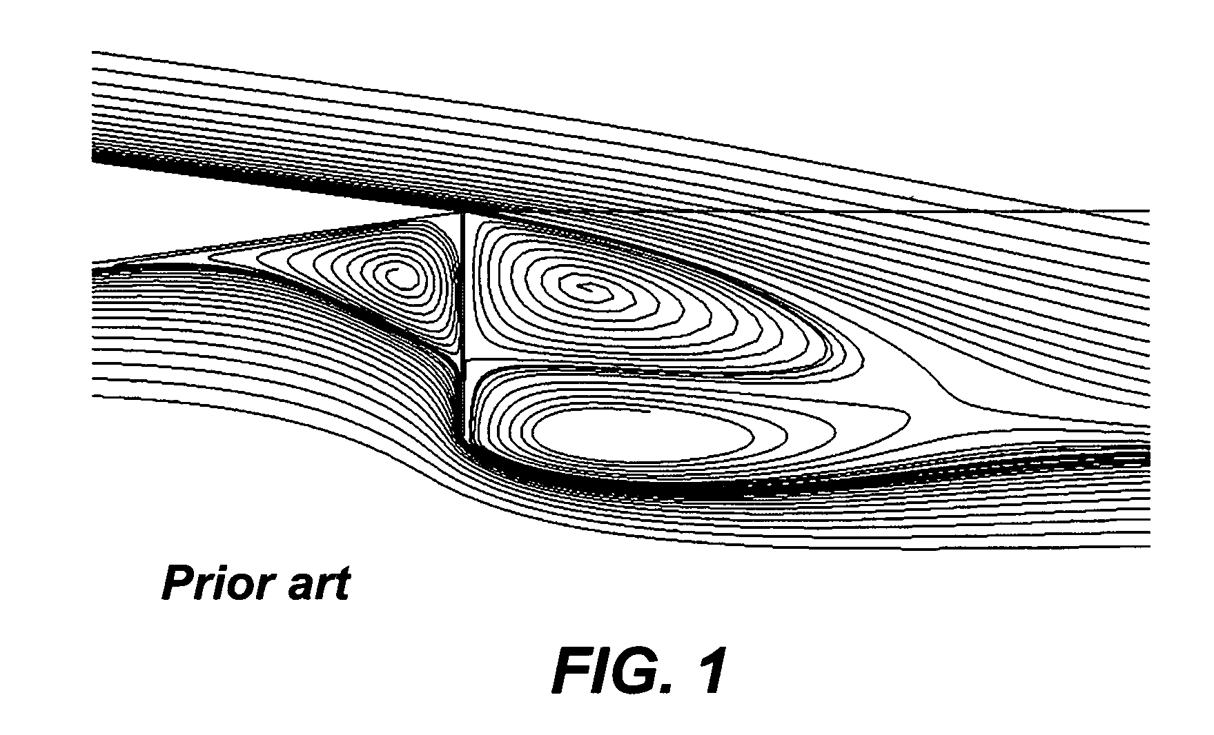
[0029] Miniature trailing edge (MiTE) devices have been shown to be effective in generating aerodynamic forces. In two-dimensional flow, a 1.5% chord vertically-deflected device can change the section lift coefficient, C1, as much as 0.33. This is equivalent to deflecting a 10% chord conventional flap 15 degrees. FIG. 1 depicts streamlines on MiTE deflected at 90-degrees that shows the stagnation pressure map and the streamline for an NACA0012 airfoil with a 1.5% flap. As shown, the separated region behind the trailing edge is mainly re...


PUM


Abstract

Improved miniature trailing edge effectors for aerodynamic control are provided. Three types of devices having aerodynamic housings integrated to the trailing edge of an aerodynamic shape are presented, which vary in details of how the control surface can move. A bucket type device has a control surface which is the back part of a C-shaped member having two arms connected by the back section. The C-shaped section is attached to a housing at the ends of the arms, and is rotatable about an axis parallel to the wing trailing edge to provide up, down and neutral states. A flip-up type device has a control surface which rotates about an axis parallel to the wing trailing edge to provide up, down, neutral and brake states. A rotating type device has a control surface which rotates about an axis parallel to the chord line to provide up, down and neutral states.

Description

CROSS-REFERENCE TO RELATED APPLICATIONS [0001] This application is cross-referenced to and claims the benefit from U.S. patent application Ser. No. 11 / 445,086, filed on May 31, 2006 which claims the benefit from U.S. Provisional Patent Application 60 / 685,942, filed on May 31, 2005, which are hereby incorporated by reference in their entirety. STATEMENT REGARDING FEDERALLY SPONSORED RESEARCH OR DEVELOPMENT [0002] This invention was made with Government support under contract F49620-98-1-0299 from the air force and under contract NN104AA79G from NASA. The government has certain rights in this invention.FIELD OF THE INVENTION [0003] The invention relates generally to miniature aerodynamic effectors. More particularly, the invention relates to miniature aerodynamic effectors that operate at high frequency and low power. BACKGROUND [0004] Many different flap arrangements for changing the aerodynamic lift generated by an aerodynamic element of an aircraft are known. For example, the Gurne...

Claims


Application Information

Patent Timeline
IPC IPC(8): B64C9/28
CPCB64C9/18Y02T50/32Y02T50/12B64C2003/145Y02T50/10Y02T50/30
Inventor LEE, HAK-TAEBIENIAWSKI, STEFAN R.KROO, ILAN M.
Owner THE BOARD OF TRUSTEES OF THE LELAND STANFORD JUNIOR UNIV
Why Eureka
Try Eureka