Method and apparatus for Wi-Fi capacity enhancement

Inactive Publication Date: 2007-10-25
TENXC WIRELESS
View PDF6 Cites 23 Cited by
  • Summary
  • Abstract
  • Description
  • Claims
  • Application Information

AI Technical Summary

Benefits of technology

[0006] The present invention mitigates the interference problem by overlaying the coverage area with multiple directional antenn

Problems solved by technology

The number of active clients that an AP can support is limited by the CSMA/CA access protocol used in the WLAN system.
If too many clients try to access the AP, collisions may happen more frequently and th

Method used


Image

  • Method and apparatus for Wi-Fi capacity enhancement
  • Method and apparatus for Wi-Fi capacity enhancement
  • Method and apparatus for Wi-Fi capacity enhancement

Examples


Embodiment Construction

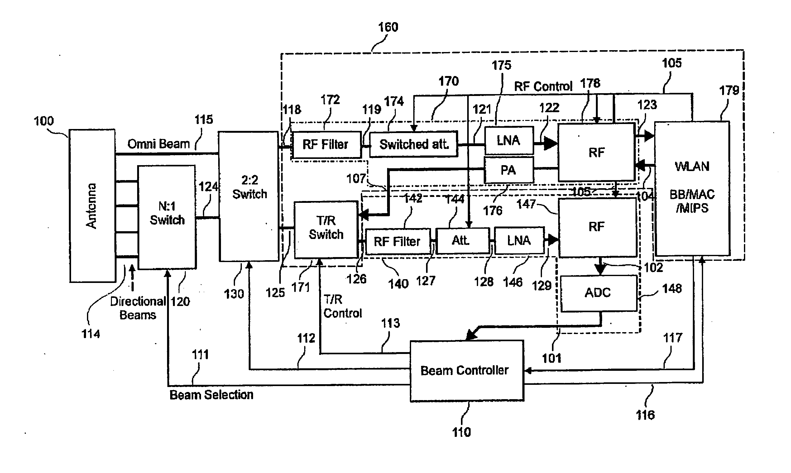
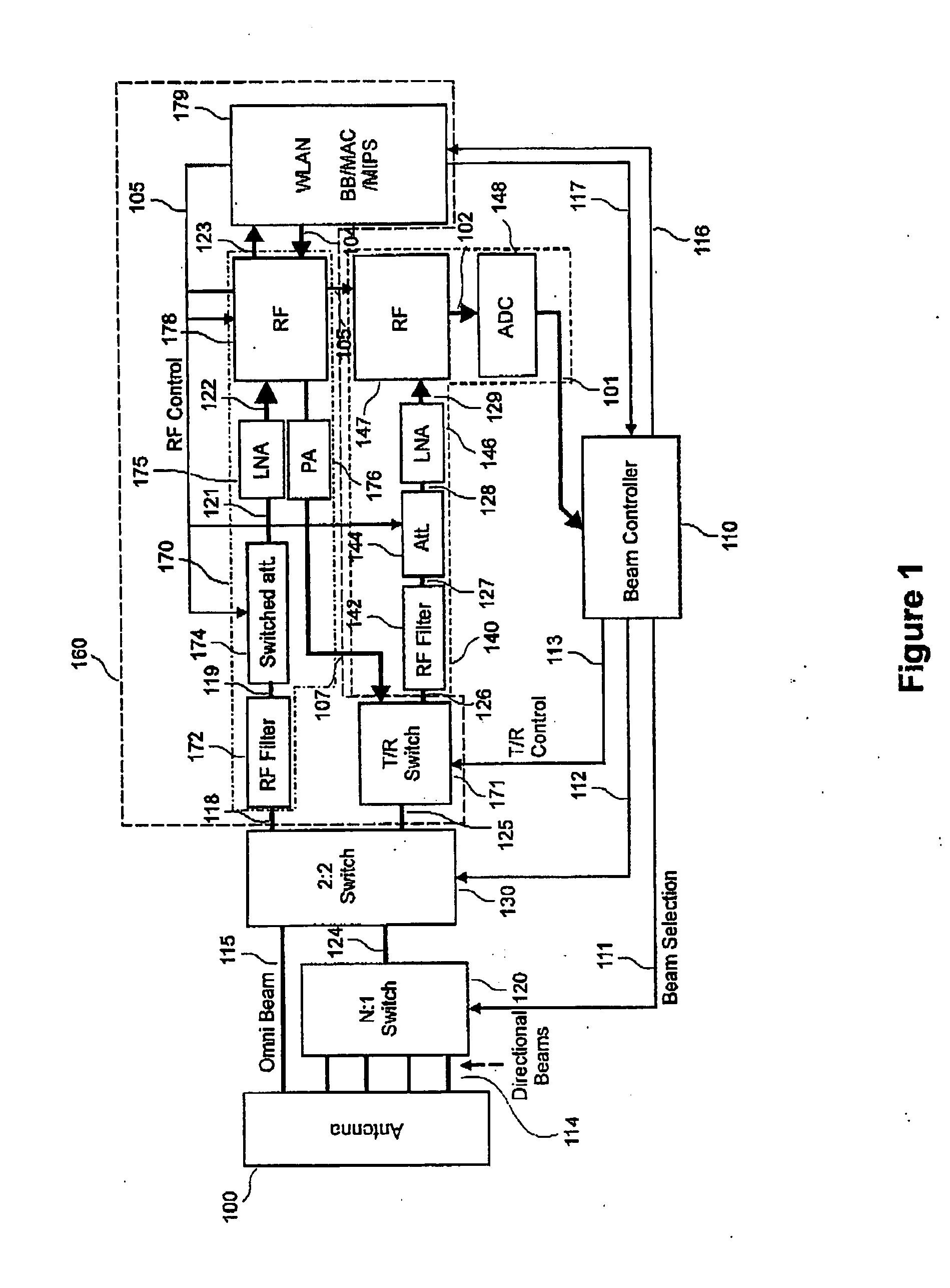
[0019]FIG. 1 shows a block diagram of an exemplary embodiment of the present invention as a system solution.

[0020] The system comprises a multiple-beam antenna 100, a plurality of beam switches 120, a 2:2 switch 130, an RF filter 142, a switched attenuator 144, a low-noise amplifier 146, an RF circuit 147, an analog to digital converter (ADC) 148, a beam controller 110, a transmit / receive (T / R) switch 171, an RF Filter 172, a switched attenuator 174, a low noise amplifier (LNA) 175, power amplifier 176, an RF integrated circuit 178, and a Wireless Local Area Network (WLAN) processor 170.

[0021] The multi-beam antenna 100 comprises an omni-directional antenna and a plurality of directional antennas. It is connected through a plurality of signals 114, to the beam switches 120. The multi-beam antenna 100 is also connected to the 2:2 switch 130 through an omni-directional beam signal 115.

[0022] The beam switches 120 are connected to the 2:2 switch 130 through a signal 124. Furthermore...


PUM


Abstract

A novel system is disclosed for WLAN applications. The inventive system mitigates the problem of interference by overlaying an omni-directional pattern with a plurality of directional beams, where each beam covers only part of the serving area defined by the omni-directional pattern. After an initial communication from the subscriber stations along the omni-directional pattern, the directional beam that provides the best signal quality is determined and the access point thereafter communicates with that subscriber station using only the beam with the best signal quality. The inventive concept can be expanded to encompass MIMO WLAN systems.

Description

FIELD OF THE INVENTION [0001] The present invention relates to communication in a WLAN (Wireless Local Area Network) system from the access point, more particularly it relates to WLAN communication using multiple beams. BACKGROUND TO THE INVENTION [0002] WLAN is the name sometimes given to the 802.11 wireless telecommunications standard developed by the IEEE. It was intended to be used for wireless communications between portable devices and a local real network. It enables a person with a WLAN-enabled computer or personal digital assistant (PDA) to connect to the Internet when in proximity to an access point (AP). The geographical region covered by one or several access points is typically referred to as a hotspot. WLAN is also referred to as wi-Fi, is the name of an industry consortium that certifies WLAN systems. [0003] A typical Wi-Fi hotspot contains one or more Access Points (APs) and one or more clients, also referred to as subscriber stations (SS). An AP broadcasts its Servi...

Claims


Application Information

Patent Timeline
IPC IPC(8): H04M1/00H04W16/28H04W84/12
CPCH04W84/12H04W16/28
Inventor GAO, SHIWEITRIGUI, HAFEDH
Owner TENXC WIRELESS
Why Eureka
Try Eureka