Image-Taking Apparatus and Image-Taking Method

a technology of image-taking apparatus and storage means, which is applied in the direction of color television details, television system details, television systems, etc., can solve the problems of lack of generality, rising manufacturing costs, and inability to meet the needs of users, so as to prevent the cost of manufacturing the image-taking apparatus from rising, the storage capacity of the storage means can be reduced.

Active Publication Date: 2008-02-28
SONY CORP
View PDF15 Cites 18 Cited by
  • Summary
  • Abstract
  • Description
  • Claims
  • Application Information

AI Technical Summary

Benefits of technology

[0022] That is to say, in accordance with the image-taking apparatus provided by the present invention, if the data of an image is supplied to the first compression / coding means at the first screen rate, the second compression / coding means carries out a compression / coding process on an image obtained as a result of a decompression / decoding process, which is carried out by the decompression / decoding means, at the second screen rate lower than the first screen rate, and the storage means is used for storing the data of an image obtained as a result of the compression / coding process carried out by the second compression / coding means. If the second screen rate is the contemporary standard rate, for example, the data of an image taken in an image-taking process can be obtained at a screen rate higher than the standard rate. Thus, even in the case of such an image, the existing circuits can be used as the decompression / decoding means and the storage means. In addition, the storage means can be used for storing the data of an image in the contemporary video format conforming to the standard rate. On top of that, the first compression / coding means receives data of an image, which has been taken in an image-taking process at a first screen rate, and carries out a compression / coding process on the image whereas the temporary storage means is used for temporarily storing the data of an image obtained as a result of the compression / coding process carried out by the first compression / coding means. Thus, the storage capacity of the storage means can be reduced. As a result, it is possible to prevent the cost of manufacturing the image-taking apparatus from rising and to store the data of an image taken at a screen rate higher than the standard rate in the contemporary video format.

Problems solved by technology

In consequence, there are problems such as a rising manufacturing cost and a lack of generality.
In addition, as shown in an invention described in Patent Document 2 mentioned above, there are problems such as a rising cost to manufacture the circuit for parallel processing and lost portability.

Method used


Image

  • Image-Taking Apparatus and Image-Taking Method
  • Image-Taking Apparatus and Image-Taking Method
  • Image-Taking Apparatus and Image-Taking Method

Examples


Embodiment Construction

[0028] An embodiment of the present invention is explained by referring to diagrams as follows.

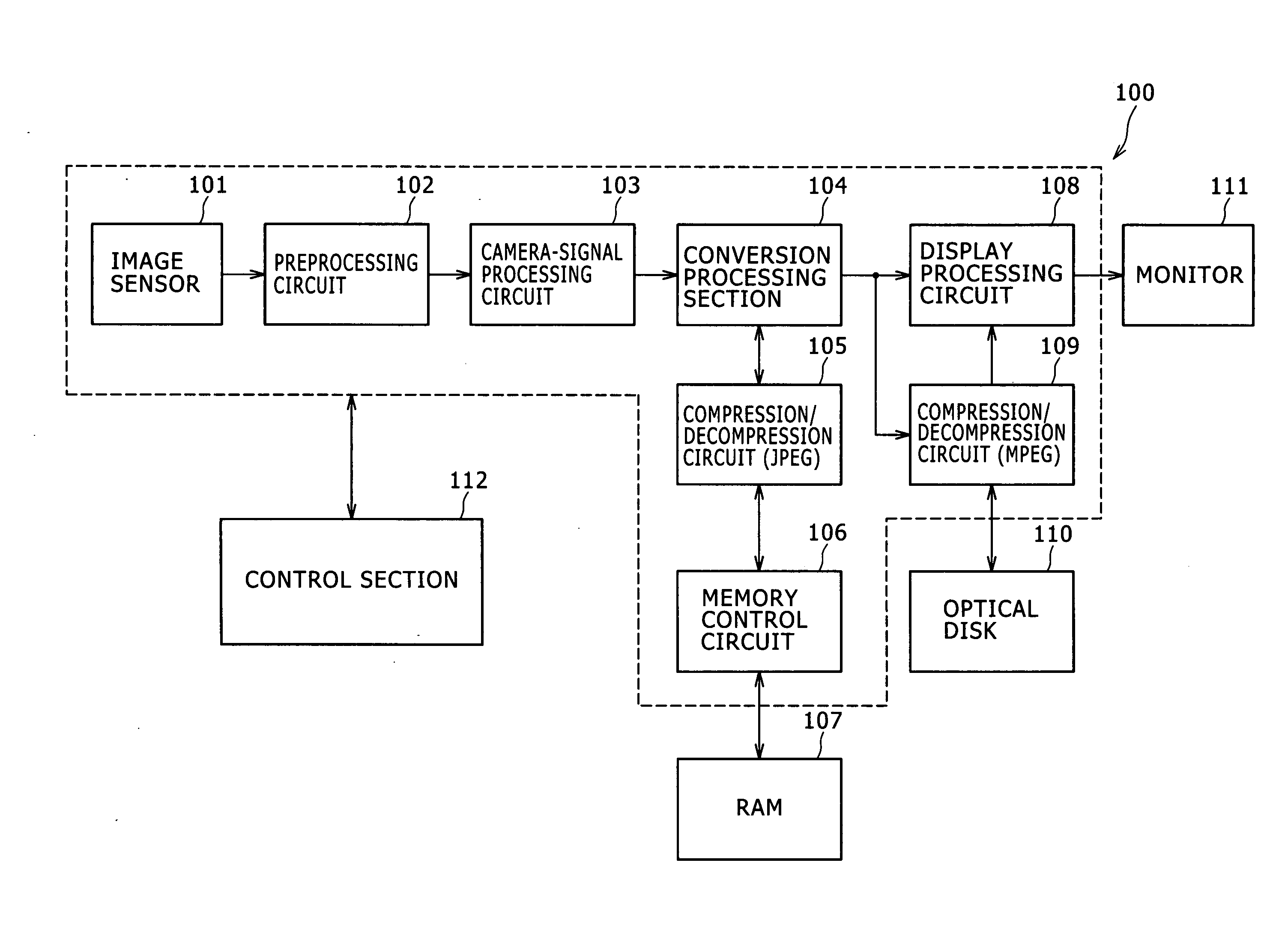
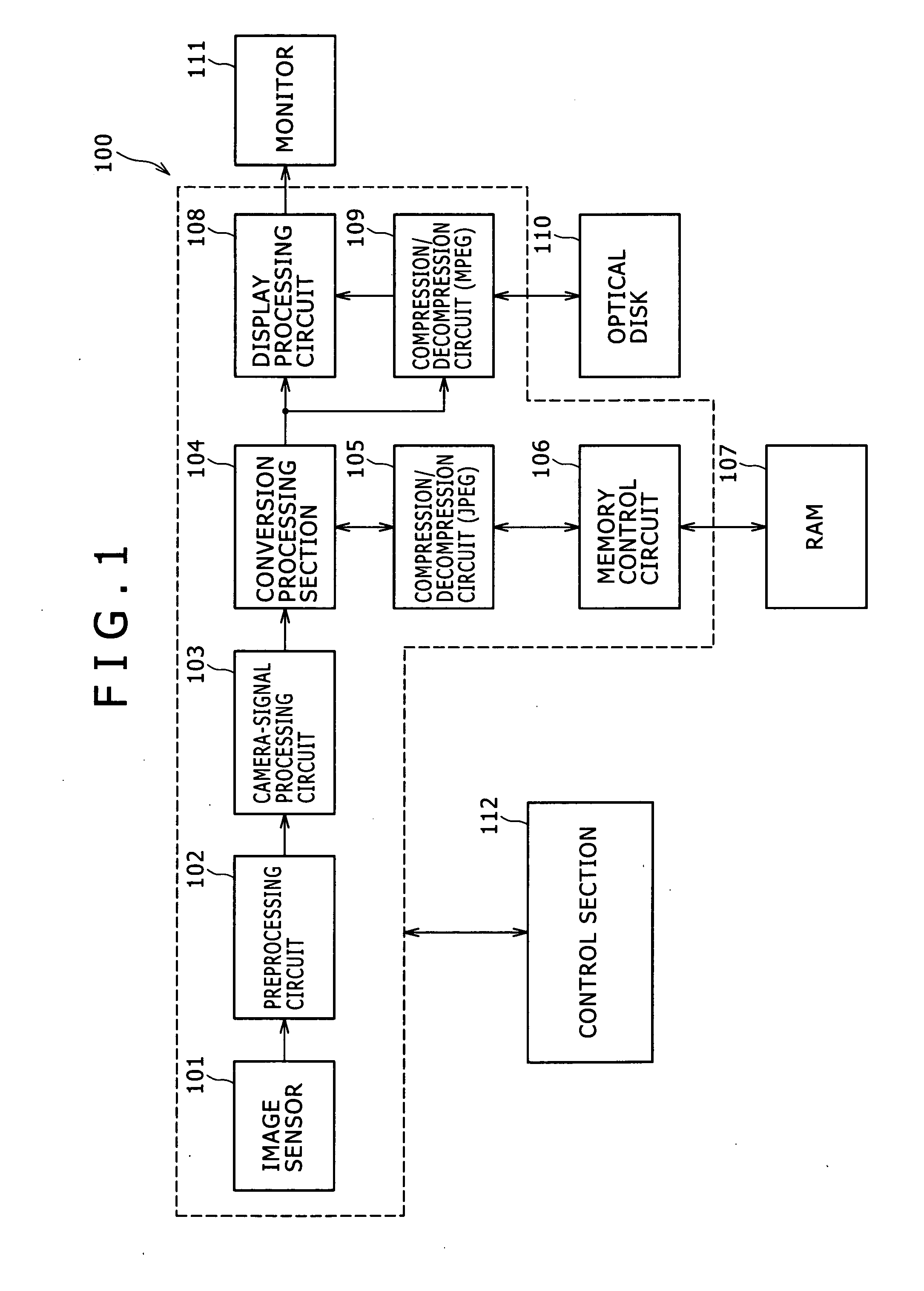
[0029]FIG. 1 is a diagram showing a typical system configuration of an image-taking apparatus 100 according to the embodiment. The image-taking apparatus 100 shown in FIG. 1 includes an image sensor 101, a preprocessing circuit 102, a camera-signal processing circuit 103, a conversion processing section 104, compression / decompression circuits 105 and 109, a memory control circuit 106, a RAM 107, a display processing circuit 108, an optical disk 110, a monitor 111 and a control section 112.

[0030] The image sensor 101 is a unit for carrying out a photoelectric conversion process to convert a light beam generated by an object of photographing and received by components including a lens unit employed in the image-taking apparatus 100 into an electrical signal. The image sensor 101 is typically an image-taking device of a CMOS (Complementary Metal Oxide Semiconductor) type. The image sensor 1...


PUM


Abstract

An image obtained as a result of an image-taking process carried out at a screen rate higher than a standard screen rate is stored in a recording medium in the contemporary video format. To put it more concretely, the image obtained as a result of an image-taking process is supplied at a first screen rate to first compression/coding means for carrying out a compression/coding process at the first screen rate and image data obtained as a result of the compression/coding process is temporarily stored in temporary storage means. After image data output by the first compression/coding means during a predetermined period of time is stored in the temporary storage means, decompression/decoding means reads out the image data from the temporary storage means at a second screen rate lower than the first screen rate, carries out a decompression/decoding process on the image data and stores a result of the decompression/decoding process in recording means.

Description

TECHNICAL FIELD [0001] The present invention relates to an image-taking apparatus and an image-taking method. More particularly, the present invention relates to an image-taking apparatus and an image-taking method, which are used for taking an image by using a solid-state image-taking device. BACKGROUND ART [0002] In recent years, accompanying severer and severer competition between image-taking apparatus represented by digital cameras, in the field of image-taking apparatus for consumer applications, there are demands for better qualities, larger-scale integrations and more advanced functions. For this reason, special functions provided for only business applications so far have also started becoming popular in the consumer applications. A representative example of the special functions is a high-speed image-taking function for taking an image at an image-taking rate higher than a normal rate. [0003] In the conventional image-taking apparatus, the size of an image to be processed ...

Claims


Application Information

Patent Timeline
Patent Type & Authority Applications(United States)
IPC IPC(8): H04N5/76H04N5/225H04N5/335H04N5/341H04N5/374H04N5/92H04N7/26H04N19/00H04N19/423H04N19/587H04N21/41H04N21/4223H04N21/426H04N21/433H04N21/4402
CPCH04N5/77H04N5/772H04N5/781H04N5/85H04N5/907H04N5/91H04N21/440281H04N9/8042H04N21/4122H04N21/4223H04N21/42646H04N21/4334H04N9/7921H04N5/92H04N23/00
Inventor TSUJIMURA, TAKASHIENOMOTO, TAKUROYONEDA, YUTAKAFUKUNAGA, MASATSUGUMIYAKOSHI, DAISUKEIKEDA, NOBUHOKUBO, MANABU
Owner SONY CORP
Why Eureka
Try Eureka