

Fuel Cell System
a fuel cell and system technology, applied in the field of fuel cell systems, can solve the problems of fuel system malfunction, fuel system failure to provide desired power generation performance or specified performance, fuel system heat dissipation and cooling, etc., to achieve the effect of preventing water freezing, ensuring safety and easy maintenance/upkeep of its operating functions, and restricting a lack of maneuverability
- Summary
- Abstract
- Description
- Claims
- Application Information
AI Technical Summary
Benefits of technology
Problems solved by technology
Method used
Image

Examples
first embodiment
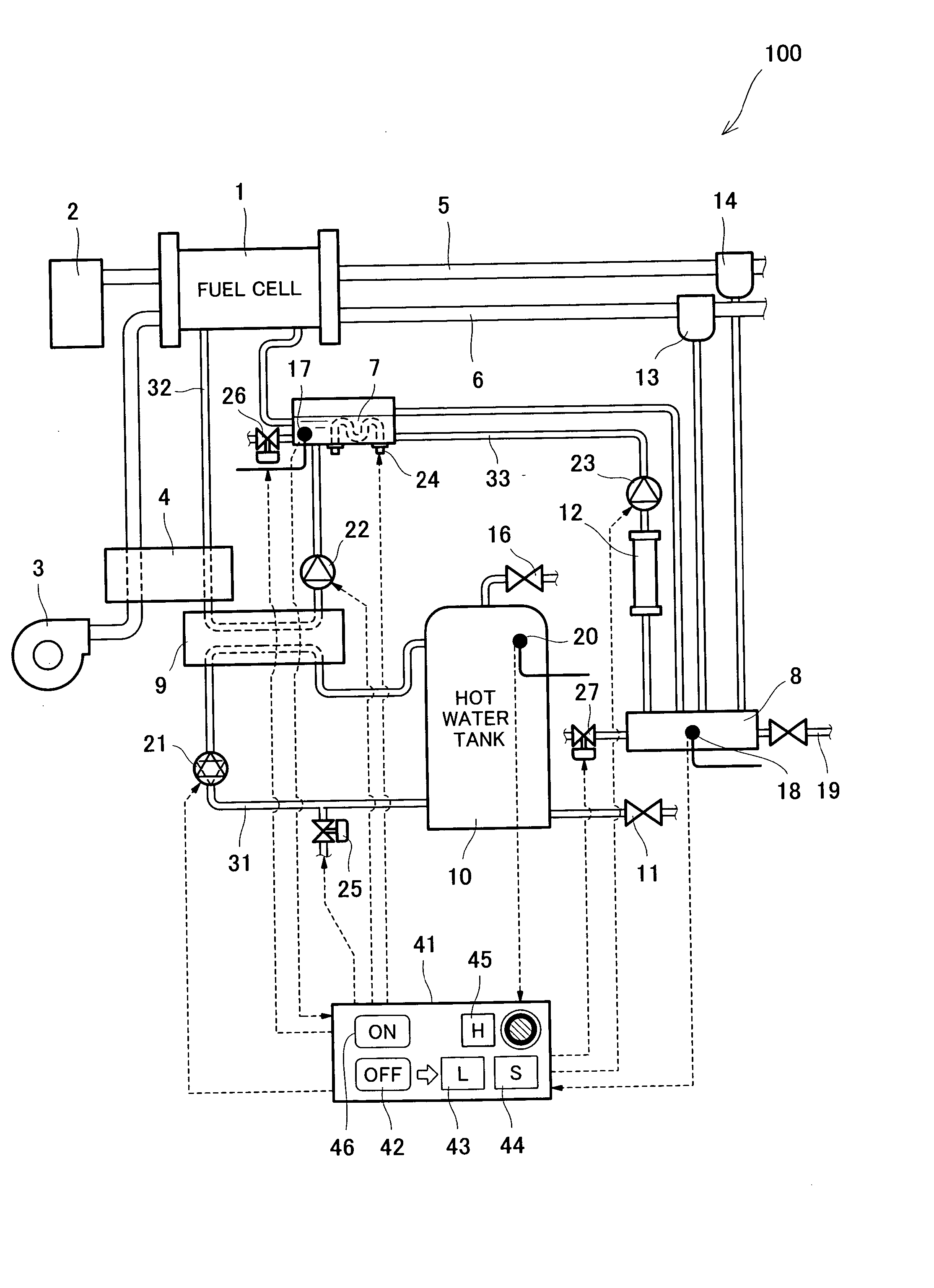
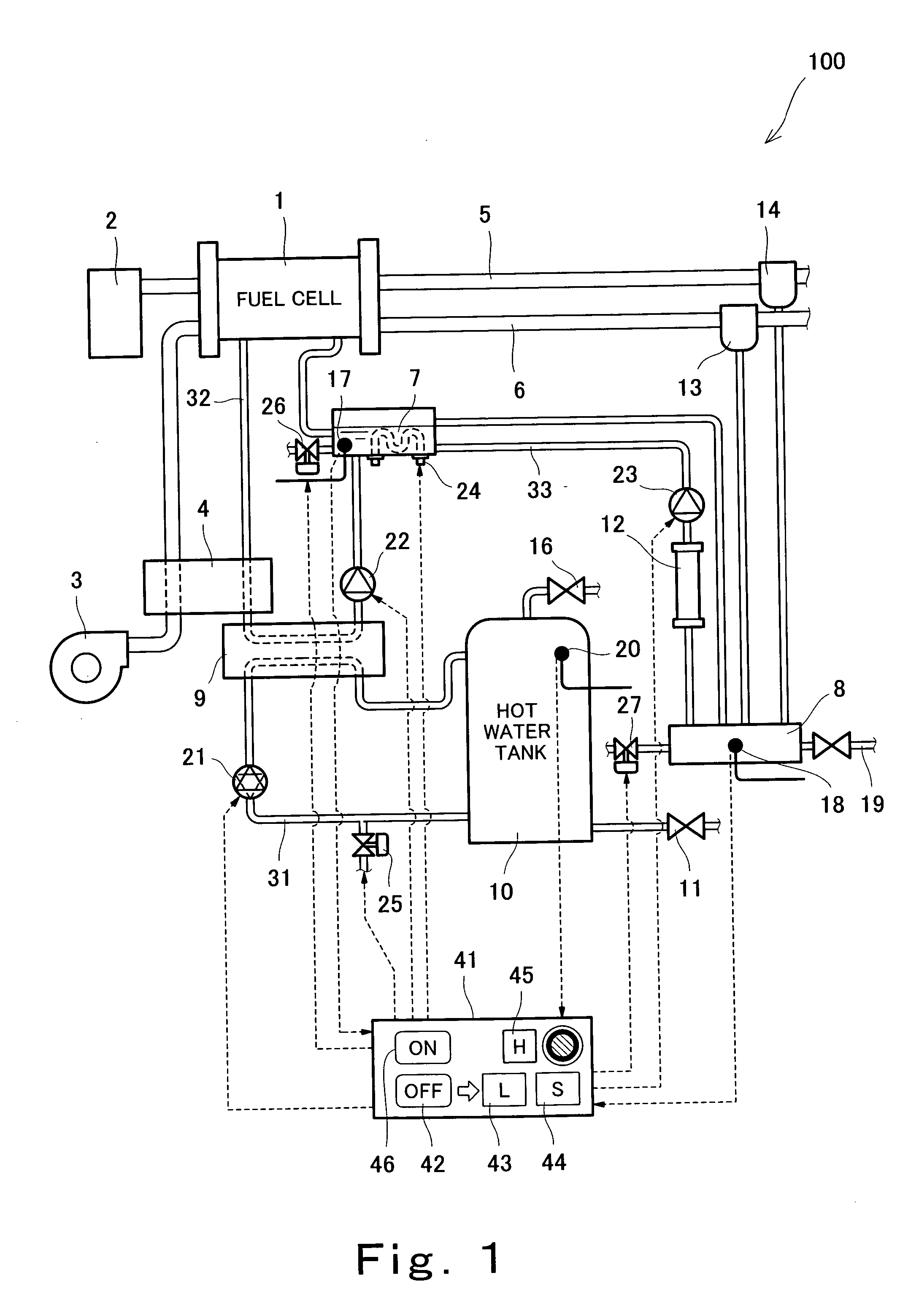
[0115]FIG. 1 is a structural diagram diagrammatically showing the configuration of a fuel cell system constructed according to a first embodiment of the invention. It should be noted that FIG. 1 illustrates only the elements necessary for explaining the concept of the invention, while omitting unessential elements.
[0116] As illustrated in FIG. 1, the fuel cell system 100 of the first embodiment of the invention includes: a fuel cell 1 having a polymer ion exchange membrane as an electrolyte membrane; a fuel feeding device 2 for supplying a hydrogen-rich fuel gas to the fuel cell 1; an oxidant feeding device 3 for suctioning air from the atmosphere and supplying it under pressure to the fuel cell 1 as an oxidizing gas containing oxygen; a humidifier 4 for humidifying and heating the air fed from the oxidant feeding device 3 utilizing vapor before it is supplied to the fuel cell 1; and a cooling water tank 7 for storing cooling water to be circulated within the fuel cell 1. The cooli...
second embodiment
[0181] A second embodiment is associated with a fuel cell system having a reformer and heater as a fuel feeding device and the heat generated by the heater is utilized for preventing water freezing.
[0182]FIG. 3 is a structural view diagrammatically showing the configuration of the fuel cell system of the second embodiment of the invention. In FIG. 3, only the elements necessary for explaining the concept of the invention are illustrated, while unessential elements and the elements that function similarly to those of the first embodiment are omitted.
[0183] In FIG. 3, the parts that correspond to those of the first embodiment are indicated by the same reference numerals as in FIG. 1.
[0184] As illustrated in FIG. 3, the fuel cell system 200 according to the second embodiment of the invention includes, as the fuel feeding device 2, a reformer 29 and a burner 28 for heating the reformer 29 to a temperature suitable for catalytic reforming and keeping it at this temperature. The reform...
third embodiment
[0198] A third embodiment of the invention is associated with an instance where water freezing is prevented by making use of heat generated by a back-up heater that is provided in an ordinary fuel cell system for maintaining the temperature of hot water stored in the hot water tank.
[0199]FIG. 4 is a structural view diagrammatically showing the configuration of a fuel cell system according to the third embodiment of the invention. In FIG. 4, only the elements necessary for explaining the concept of the invention are illustrated, while unessential elements and the elements that function similarly to those of the first and second embodiments are omitted.
[0200] In FIG. 4, the parts that correspond to those of the first embodiment are indicated by the same reference numerals as in FIG. 1.
[0201] As illustrated in FIG. 4, the fuel cell system 300 of the third embodiment of the invention has a back-up heater 15 disposed at a specified position in the hot water circulation passage 31, for...
PUM
 Abstract
Description
Claims
Application Information