Condition Detection Apparatus, Condition Detection Method, Condition Detection Program, Information Recording Medium Therefor, and Condition Display Apparatus, Condition Display Method, Condition Display Program, Information Recording Medium Therefor

a condition detection and condition display technology, applied in the direction of fluid pressure measurement by mechanical elements, solids vibration measurement, machine part testing, etc., can solve the problems of reducing operation efficiency, and reducing the service life of the linear rolling motion guide apparatus. , to achieve the effect of prolonging the service life and improving the service life of the linear rolling motion guide apparatus

Active Publication Date: 2008-03-13
THK CO LTD
View PDF7 Cites 30 Cited by
  • Summary
  • Abstract
  • Description
  • Claims
  • Application Information

AI Technical Summary

Benefits of technology

[0058] Accordingly, prognosis of occurrences of failures in the linear rolling motion guide apparatus may be performed, maintainability for a user of the linear rolling motion guide apparatus may be improved, and contributions may be made to prolonging the operation life of the apparatus and realizing performance assurance and quality improvement of apparatuses or devices manufactured by utilizing such linear rolling motion guide apparatuses.
[00

Problems solved by technology

However, when these diagnostic methods are applied to a linear rolling motion guide apparatus, the following problems are encountered.
Hence, there is a problem in which vibrations attributable to abnormalities in the operational conditions, which should normally be detected, may not be accurately detected.
Thus, there is a problem in that additional time is required until diagnosis is obtained, and the linear rolling motion guide apparatus must be temporarily shut down in order to r

Method used


Image

  • Condition Detection Apparatus, Condition Detection Method, Condition Detection Program, Information Recording Medium Therefor, and Condition Display Apparatus, Condition Display Method, Condition Display Program, Information Recording Medium Therefor
  • Condition Detection Apparatus, Condition Detection Method, Condition Detection Program, Information Recording Medium Therefor, and Condition Display Apparatus, Condition Display Method, Condition Display Program, Information Recording Medium Therefor
  • Condition Detection Apparatus, Condition Detection Method, Condition Detection Program, Information Recording Medium Therefor, and Condition Display Apparatus, Condition Display Method, Condition Display Program, Information Recording Medium Therefor

Examples


first embodiment

(II) First Embodiment

[0116] A first embodiment of the present invention, based on the above-described principle, will be specifically described with reference to FIGS. 3 to 8.

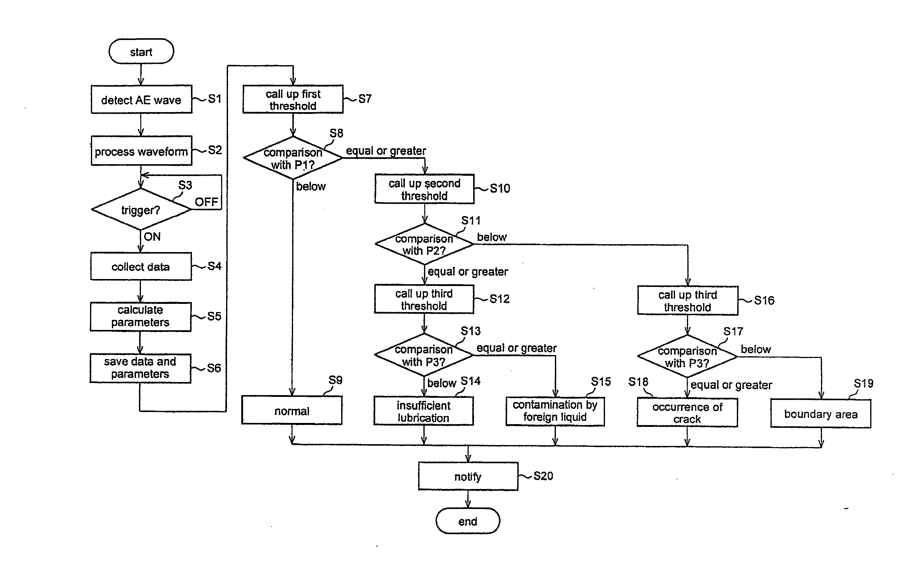
[0117] In the drawings: FIG. 3 is a block diagram showing a general structure of a condition diagnosis apparatus according to the first embodiment; FIG. 4 is an longitudinal sectional view showing a general structure of an AE sensor that detects extended AE waves according to the first embodiment; FIGS. 5 to 7 are views for describing an LM system to which the present invention is applied; and FIG. 8 shows a flowchart representing an operational condition detection processing executed by the condition diagnosis apparatus according to the first embodiment.

[0118] As shown in FIG. 3, a condition diagnosis apparatus S according to the first embodiment comprises: an AE sensor 1; a waveform shaping unit 2 including a BPF (Band Pass Filter) 2A and an envelope detection section 2B; an A / D (Analog-to-Digital) converte...

first example

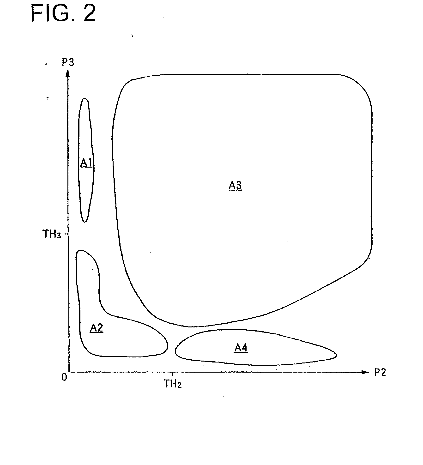
[0174] Next, in order to demonstrate the effectiveness of the above-described principle of the present invention as well as the condition detection apparatus S according to the first embodiment, an example in which a group of actual measurement data is plotted using the graph shown in FIG. 2 will be described with reference to FIGS. 9 and 10.

[0175] As for the experimental environment in which the respective points indicated below were obtained, in the case of FIG. 9, a model SNS55LR manufactured by the present applicant was used as an LM guide to which the AE sensor 1 is set. External load to the movable block was set to 0.09 C (14.7 kN), the stroke or movement distance of the movable block was set to 250 mm, movement speed of the same was set to 400 mm / sec, the sampling rate of the detection signal Sae was set to 10 kilohertz, and a measurement period of 0.4 seconds was used.

[0176] Additionally, in the case of FIG. 10, a model SHS25V manufactured by the present applicant was used...

second embodiment

(III) Second Embodiment

[0183] Next, a second embodiment of the present invention, based on the above-described principle, will be specifically described with reference to FIGS. 3 to 7 and FIGS. 11 to 13.

[0184] In the drawings: FIG. 3 is a block diagram showing a general structure of a condition diagnosis apparatus according to the second embodiment; FIG. 4 is an longitudinal sectional view showing a general structure of an AE sensor that detects extended AE waves according to the second embodiment; FIGS. 5 to 7 are views for describing an LM system to which the present invention is applied; and FIG. 11 shows a flowchart representing operational condition detection processing executed by the condition diagnosis apparatus according to the second embodiment.

[0185] As shown in FIG. 3, a condition diagnosis apparatus S according to the second embodiment comprises: an AE sensor 1; a waveform shaping unit 2 including a BPF (Band Pass Filter) 2A and an envelope detection section 2B; an A / ...


PUM


Abstract

A condition detection apparatus comprising an AE sensor 1 that detects AE waves, which elastically-occur when a plurality of balls included in an LM system self-rotate and revolve within a circulation section at the same time, and generates detection signals Sae, and a signal processing unit 4 that generates a first parameter indicating an intensity of the AE waves based on the generated detection signals Sae, generates based on the detection signals Sae a second parameter by weighting only detection signals Sae temporally-continuously detected among the detection signals Sae, generates based on the detection signals Sae a third parameter by weighting only detection signals Sae temporally-discontinuously detected in correspondence with the movement of the balls among the detection signals Sae, and judges contents of an operational condition of the LM system using any one of the first, second or third parameter, is provided to enable prognosis of occurrences of failures in the LM system, to improve maintainability for a user of the LM system, and to contribute to the prolonging of the operation life of the LM system as well as performance assurance and quality improvement of apparatuses or devices incorporated with the LM system.

Description

TECHNICAL FIELD [0001] The present invention is in a technical field of a condition detection apparatus, a condition detection method, a condition detection program, and an information recording medium therefor. More particularly, the present invention is in a technical field concerning a condition detection apparatus and method for detecting an operational condition of a linear rolling motion guide apparatus during operation thereof, a condition detection program for detecting such an operational condition, and also concerning an information recording medium on which the condition detection program is recorded so as to be computer-readable. [0002] In addition, the present invention is in a technical field of a condition display apparatus, a condition display method, a condition display program, and an information recording medium therefor. More particularly, the present invention is in a technical field concerning a condition display apparatus and method for displaying an operation...

Claims


Application Information

Patent Timeline
IPC IPC(8): G06F11/30F16C29/00G21C17/00
CPCF16C29/00G01M13/045F16C29/0633F16C2233/00
Inventor YOSHIOKA, TAKEOHONJO, YOSHIYUKIWATANABE, SHIGEO
Owner THK CO LTD
Why Eureka
Try Eureka