Vehicle and control method of vehicle

US20080076629A1Inactive Publication Date: 2008-03-27TOYOTA JIDOSHA KK
6 Cites 17 Cited by

Patent Information

Authority / Receiving Office
US · United States
Current Assignee / Owner
Publication Date
2008-03-27
Estimated Expiration
Not applicable · inactive patent

Smart Images

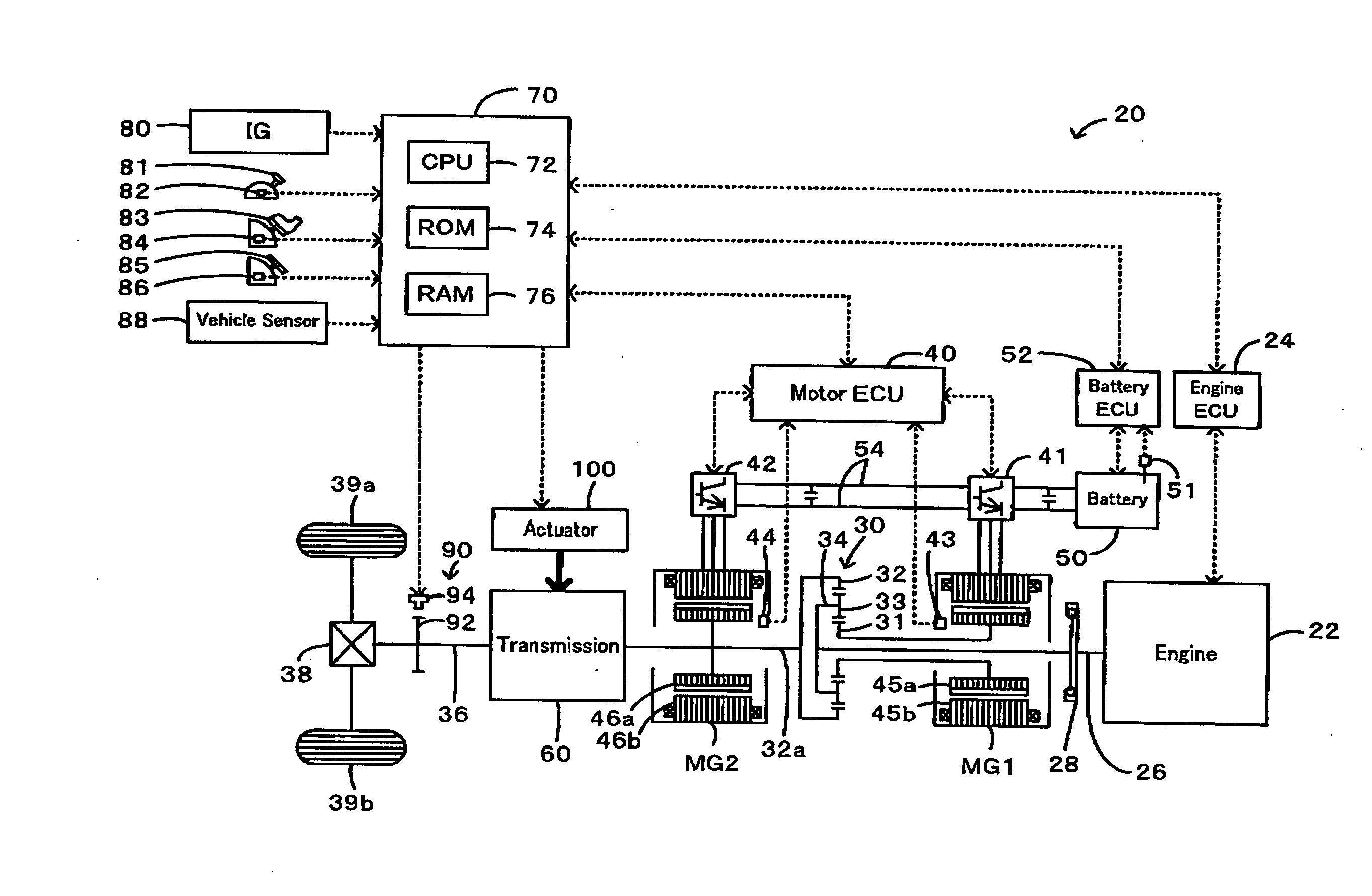
  • Figure 1
    Figure 1
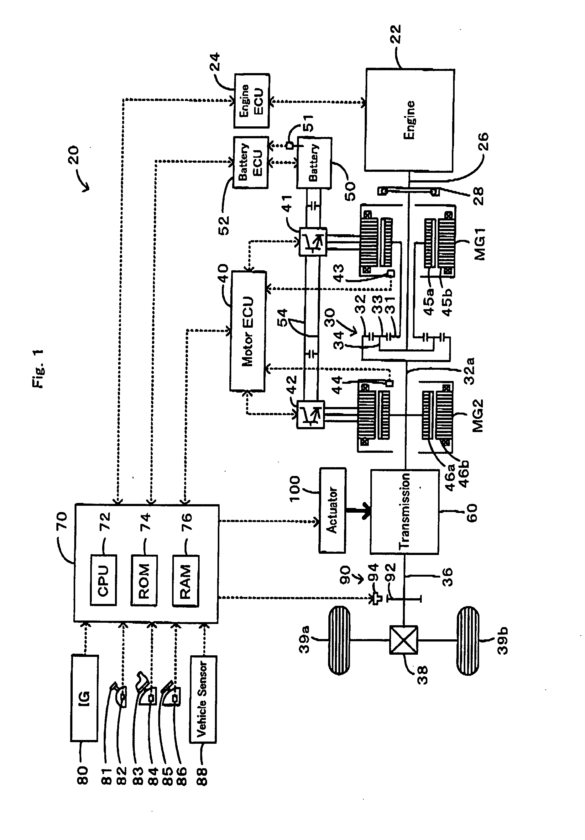
  • Figure 2
    Figure 2
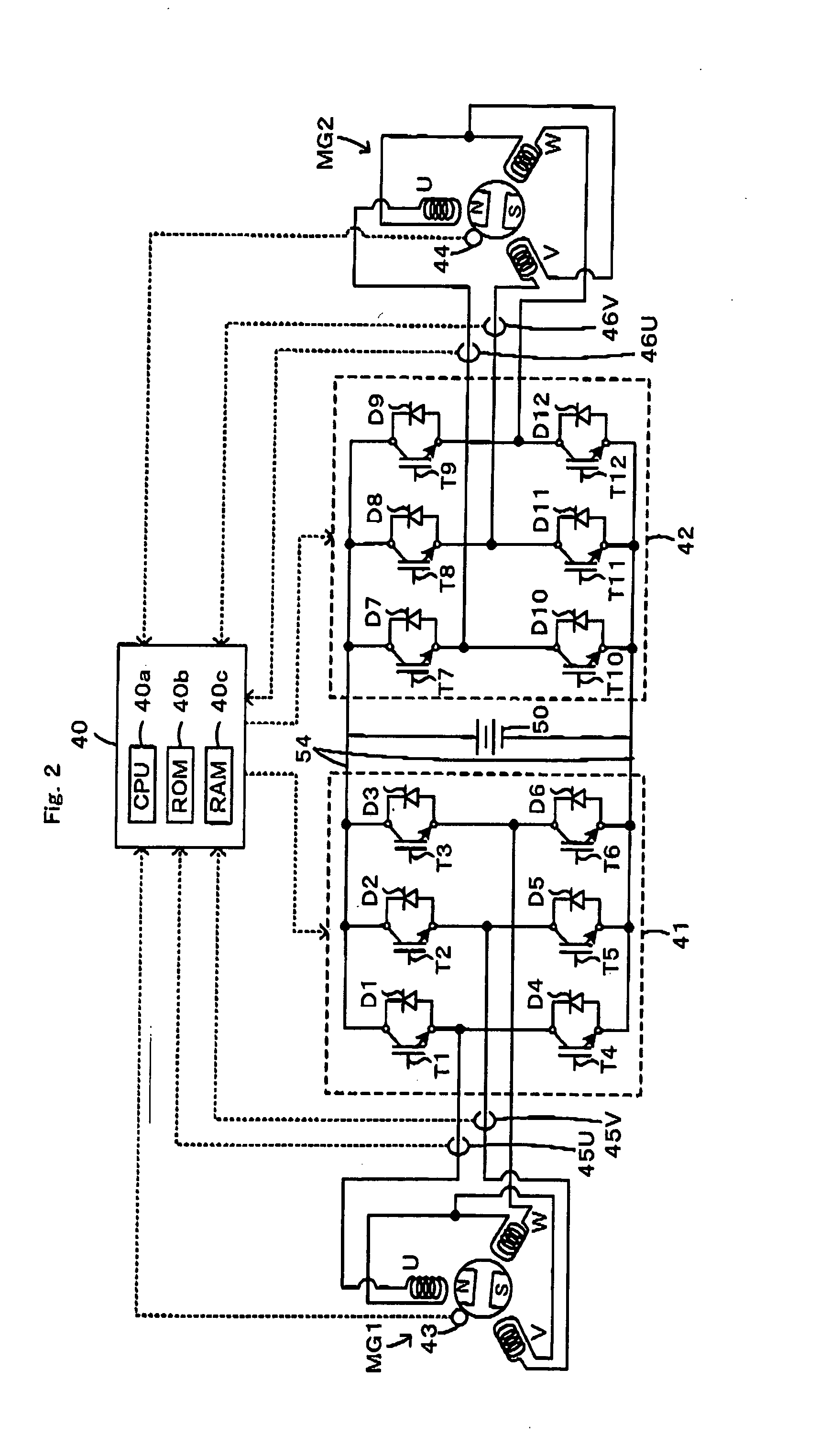
  • Figure 3
    Figure 3
Patent Text Reader

Abstract

In response to a change of a gearshift position from a parking position to a driving position, the control system of the invention connects a power shaft with a driveshaft linked to drive wheels (steps S310 and S380), while performing rotation restriction control to form a fixed magnetic field on a stator of a second motor and thereby prohibit rotation of a rotor in the second motor (step S300). This arrangement desirably restrains rotation of the power shaft and accordingly prevents the occurrence of a shock in the course of connection of the power shaft with an axle.
Need to check novelty before this filing date? Find Prior Art

Description

BACKGROUND OF THE INVENTION

[0001] 1. Field of the Invention

[0002] The present invention relates to a vehicle and a control method of the vehicle.

[0003] 2. Description of the Related Art

[0004] One proposed structure of the vehicle is equipped with an engine, a planetary gear mechanism having a carrier connected to the engine and a ring gear connected to a drive wheels via an automatic multistage transmission, a first motor linked to a sun gear of the planetary gear mechanism, and a second motor linked to the ring gear of the planetary gear mechanism (see, for example, Patent Document 1).

[0005] Patent Document 1: Japanese Patent Laid-Open Gazette No. 2005-264762 SUMMARY OF THE INVENTION

[0006] In the vehicle of this prior art structure, in the setting of a gearshift position to a parking position, the multistage transmission works to disconnect the ring gear from drive wheels. In the setting of the gearshift position to a driving position, such as a drive position, the multistage...

Examples

Embodiment Construction

[0052] One mode of carrying out the invention is described below as a preferred embodiment. FIG. 1 schematically illustrates the configuration of a hybrid vehicle 20 in one embodiment of the invention. As illustrated, the hybrid vehicle 20 of the embodiment includes an engine 22, a three shaft-type power distribution integration mechanism 30 that is linked to a crankshaft 26 or an output shaft of the engine 22 via a damper 28, a motor MG1 that is linked to the power distribution integration mechanism 30 and has power generation capability, a motor MG2 that is linked to a ring gear shaft 32a or a power shaft connected to the power distribution integration mechanism 30, a transmission 60 that converts power of the ring gear shaft 32a and outputs the converted power to a driveshaft 36 connected to drive wheels 39a and 39b, a parking lock mechanism 90 that locks the drive wheels 39a and 39b, and a hybrid electronic control unit 70 that controls the operations of the whole hybrid vehicle...