
Tool and method for fixing installation object on wheel

a technology for installing objects and tools, applied in the direction of hose connections, instruments, ways, etc., can solve the problems of fixing tools that are broken, the housing breaks, and the looseness cannot be easily observed over a long time period, so as to prevent the housing from breaking and reduce the rotation of the housing

Inactive Publication Date: 2010-07-27
THE YOKOHAMA RUBBER CO LTD
View PDF23 Cites 3 Cited by
  • Summary
  • Abstract
  • Description
  • Claims
  • Application Information

AI Technical Summary

Benefits of technology

Prevents housing breakage and ensures the installation object remains securely attached to the wheel rim well portion during vehicle travel, eliminating the need for frequent tire removal and maintenance.

Problems solved by technology

For a tool for fixing an installation object, such as the above described measuring device, on the rim well portion of the wheel, it is required that attaching and detaching work is easy, and furthermore, that looseness will not easily occur over a long time period, in a state where the object is installed.
When a worm screw is tightened up in a state where the band provided with a worm screw mechanism is looped around the rim well portion, however, a housing is rotated by a tightening torque of the worm screw, a stress concentrates on a part where the housing and the band are jointed to each other, and the stress sometimes causes breakage of the housing.
Additionally, if fixing of the installation object is completed without recognizing the breakage of the housing, there is a possibility that the fixing tool is broken down and the installation object is detached from the rim well portion during traveling of a vehicle.

Method used


Image

  • Tool and method for fixing installation object on wheel
  • Tool and method for fixing installation object on wheel
  • Tool and method for fixing installation object on wheel

Examples


Embodiment Construction

[0023]Hereinbelow, detailed descriptions will be given of configurations of the present invention with reference to the accompanying drawings. The same reference numerals and symbols designate the same elements throughout the drawings, and duplicated detailed descriptions on the same elements will be omitted.

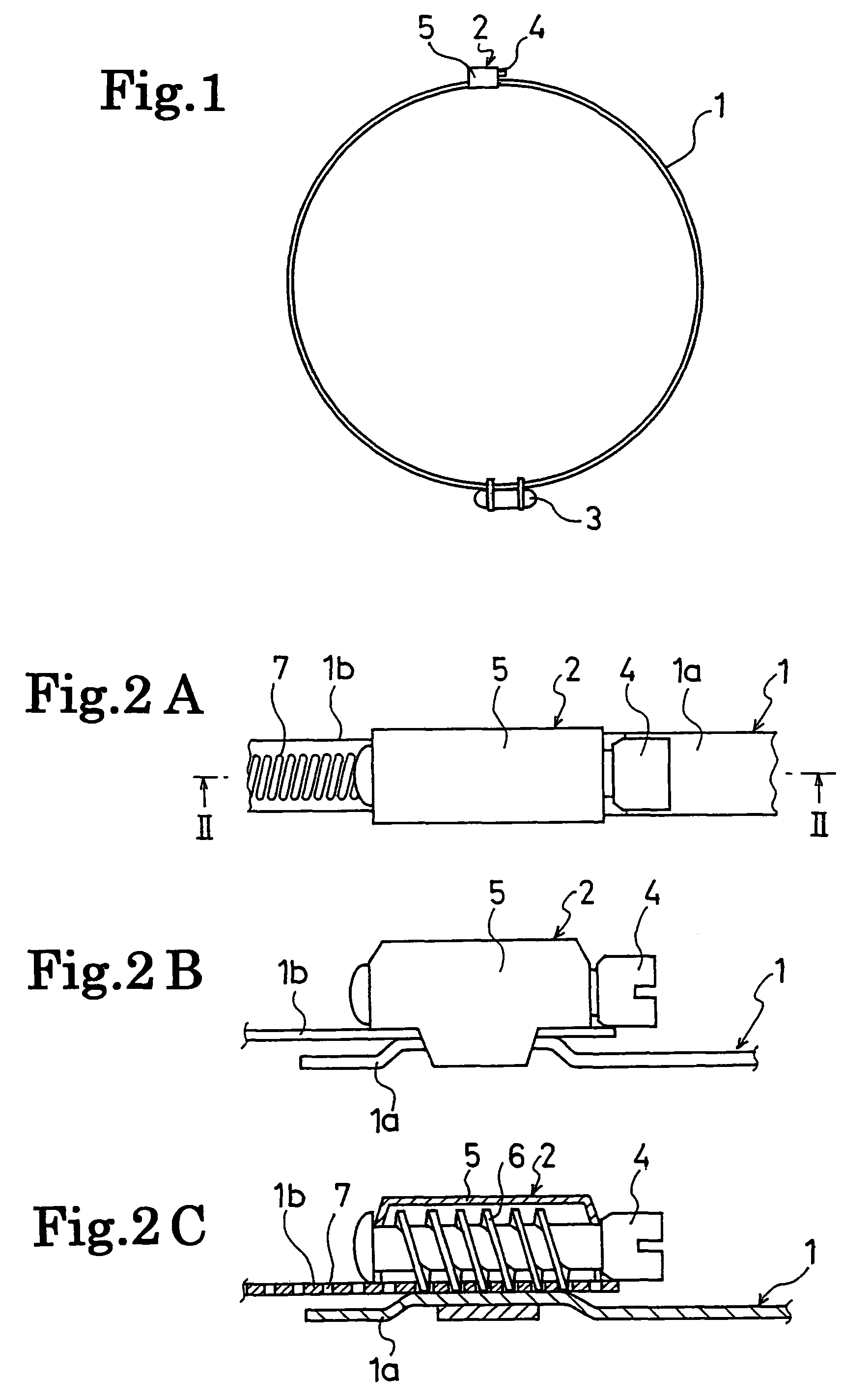
[0024]FIG. 1 schematically shows a tool for fixing an installation object on a wheel, according to the present invention. In FIG. 1, a band 1 is looped around a rim well portion of the wheel, and both end portions of the band 1 are configured to be fastened to each other by means of a worm screw mechanism 2. While this band 1 may continues as one body around an entire circumference of the rim well portion, the band 1 may be obtained by jointing plural divided band pieces with one another along the rim well portion. It is preferable that stainless steel is used as a material forming the band 1.

[0025]An installation object 3 is fixed to the band 1. The installation object 3 is not...


PUM


Abstract

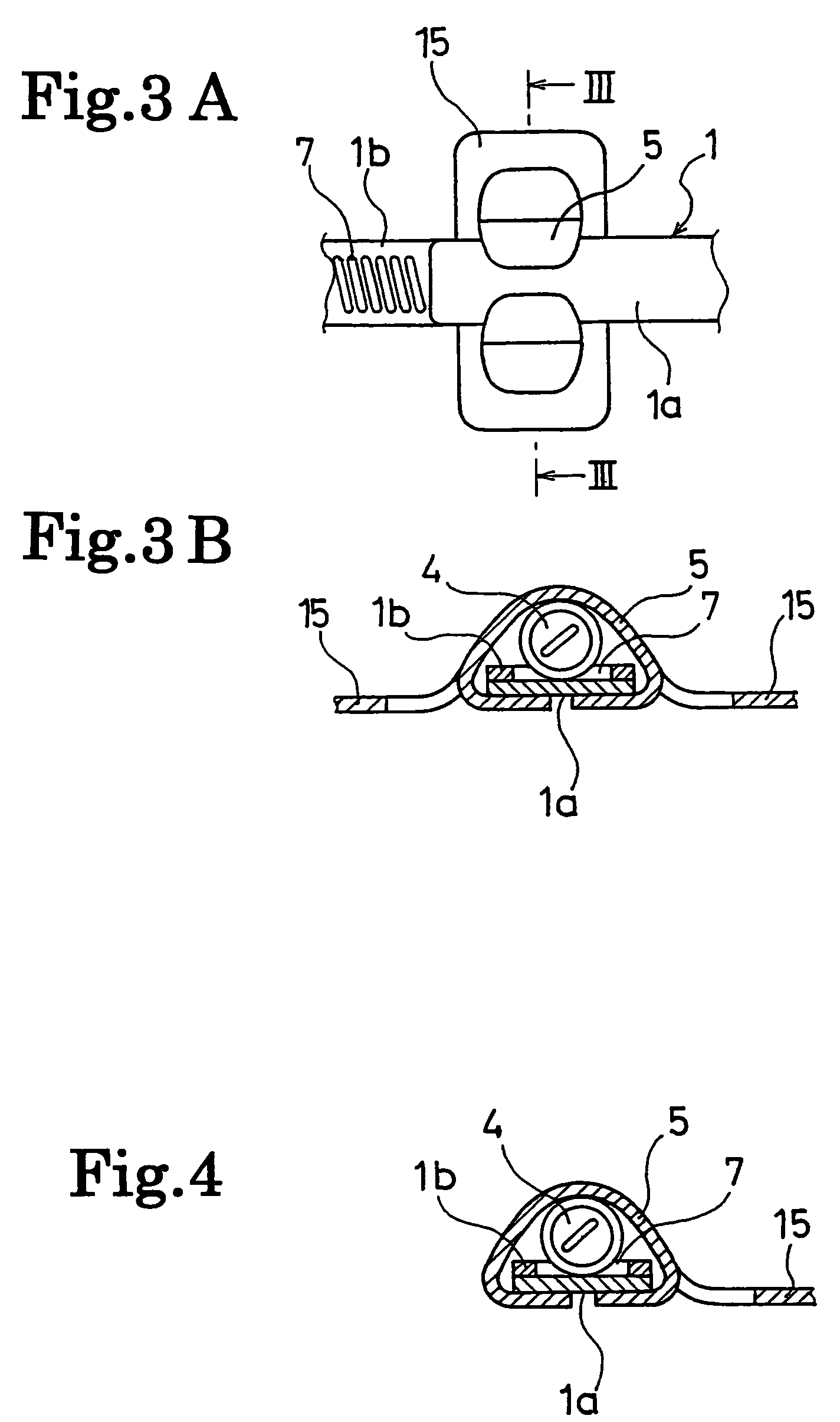
An apparatus and method for fixing an installation object on a wheel, which are enabled to restrain rotation of a housing caused by a tightening torque of a worm screw, and to thereby prevent breakage of the housing. The apparatus for fixing an installation object on a wheel includes a band which is looped around a rim well portion of the wheel and holds the installation object. While a housing for holding a worm screw is fixed to one end portion of the band, a plurality of slits for engaging with a thread of the worm screw are provided in the other end portion of the band. The apparatus includes a rotation restraining mechanism which projects more outward than the housing in a width direction of the band, and restrains rotation of the housing caused by a tightening torque of the worm screw.

Description

TECHNICAL FIELD[0001]The present invention relates to a tool and a method for fixing an arbitrary installation object on a rim well portion of a wheel. More specifically, the present invention relates to a tool and a method for fixing an installation object on a wheel, which are configured to prevent rotation of a housing caused by a tightening torque of a worm screw, and are thereby enabled to prevent breakage of the housing in a portion corresponding to the worm screw.BACKGROUND ART[0002]For the purpose of collecting physical quantities such as an air pressure of a pneumatic tire, and a temperature inside an air chamber of the tire, a measuring device, which has various sensors mounted therein, on a rim well portion of a wheel, has been installed (refer to, for example, Patent Document 1).[0003]For a tool for fixing an installation object, such as the above described measuring device, on the rim well portion of the wheel, it is required that attaching and detaching work is easy, a...

Claims


Application Information

Patent Timeline
Patent Type & Authority Patents(United States)
IPC IPC(8): F16L33/08G01M17/02B60C23/04B60B21/12
CPCB60C23/0408F16L33/08Y10T24/1427B60C23/04985
Inventor SHIMURA, KAZUHIRO
Owner THE YOKOHAMA RUBBER CO LTD
Learn More