Turbocharger

a technology of turbocharger and wastegate valve, which is applied in the direction of combustion engines, non-positive displacement fluid engines, pump control, etc., can solve the problems of frictional sounds, and achieve the effect of restrainting the rotation of the wastegate valve and suppressing the nois

Active Publication Date: 2017-04-25
IHI CORP
View PDF14 Cites 9 Cited by
  • Summary
  • Abstract
  • Description
  • Claims
  • Application Information

AI Technical Summary

Benefits of technology

[0010]An object of the present invention is to provide a turbocharger capable of achieving a noise suppressing effect by use of a simpler mechanism which restrains rotation of a wastegate valve while swingably supporting the wastegate valve.
[0016]The present invention makes it possible to achieve a noise suppressing effect by use of a simpler mechanism which restrains the rotation of the wastegate valve while swingably supporting the wastegate valve.

Problems solved by technology

This rotation causes frictional sounds between the support plate and the wastegate valve or the projecting portion.
The frictional sounds are also a cause of noises.
However, a space enough for accomplishing a welding process is not present between the belleville spring and the wastegate valve or the support plate.

Method used


Image

  • Turbocharger
  • Turbocharger
  • Turbocharger

Examples


first modification

(First Modification)

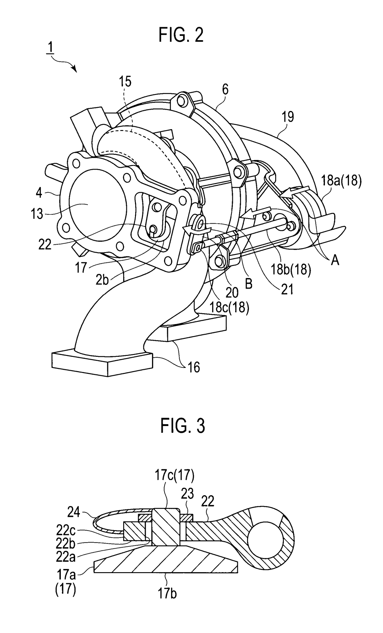
[0043]FIGS. 4A and 4B show explanatory diagrams for explaining modifications. Specifically, FIG. 4A is a cross-sectional view of a first modification, which corresponds to FIG. 3. FIG. 4B is a cross-sectional view of a second modification, which corresponds to FIG. 3.

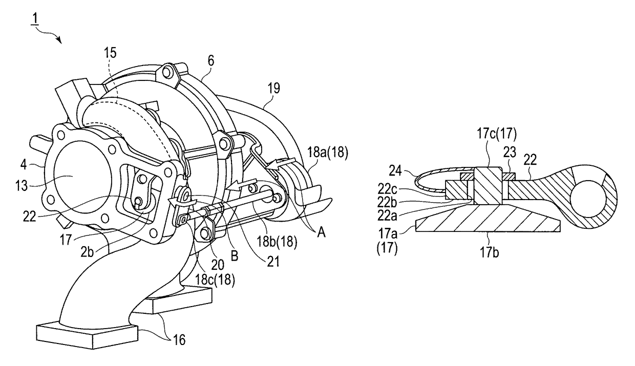
[0044]In the foregoing embodiment, the one end of the biasing portion 24 is fixed to the projecting portion 17c, while the other end of the biasing portion 24 is fixed to the support plate 22 by welding or the like. On the other hand, in the first modification, as shown in FIG. 4A, one end of a biasing portion 34 is fixed to the main body 17a, and the other end of the biasing portion 34 is fixed to the support plate 22.

[0045]To put it in detail, the one end of the biasing portion 34 is fixed to the main body 17a, while the other end of the biasing portion 34 is fixed to a position in the support plate 22 which is farther away from the main body 17a than is the surface 22b of the support plate 22 whic...

second modification

(Second Modification)

[0048]In the second modification, as shown in FIG. 4B, a biasing portion 44 is made from a coil spring. More specifically, the coil spring is a conical spring.

[0049]In the second modification, one end of the biasing portion 44 is fixed to an opposite side of the projecting portion 17c from the main body 17a with the support plate 22 interposed in between. The other end of the biasing portion 44 is fixed to a position in the support plate 22 which is farther away from the main body 17a than is the surface 22b of the support plate 22 which faces the main body 17a. To put it specifically, the position is located on a surface 22d which is opposite to the surface 22b.

[0050]In FIG. 4B, the biasing portion 44 is fixed while being compressed in a vertical direction from the state under no load. For this reason, the support plate 22 is pressed against the main body 17a by the biasing force in a direction to expand the biasing portion 44.

[0051]Like the foregoing embodime...


PUM


Abstract

A turbocharger includes: a turbine housing including a through-hole through which a turbine impeller is bypassed; and a wastegate valve configured to open and close the through-hole. A biasing portion biases the wastegate valve and a support plate in opposite directions, and restrains rotation of the wastegate valve relative to the support plate.

Description

CROSS REFERENCE TO RELATED APPLICATIONS[0001]This application is a continuation application of International Application No. PCT / JP2013 / 051957, filed on Jan. 30, 2013, which claims priority to Japanese Patent Application No. 2012-017901, filed on Jan. 31, 2012, the entire contents of which are incorporated by references herein.BACKGROUND OF THE INVENTION[0002]1. Field of the Invention[0003]The present invention relates to a turbocharger.[0004]2. Description of the Related Art[0005]Turbochargers have been known as being used to increase output of engines by being connected to the engines and the like. As boost pressure of a turbocharger becomes higher, the subsequent flow rate and pressure of the exhaust gas become higher. As the torque of the turbocharger becomes higher, the boost pressure becomes much higher. As a result, the engine and the turbocharger become more likely to suffer damage. To avoid this, some turbochargers have a function of suppressing the pressure of the exhaust ...

Claims


Application Information

Patent Timeline
Patent Type & Authority Patents(United States)
IPC IPC(8): F01D17/12F04D27/00F02B37/18F01D17/10
CPCF04D27/009F01D17/105F02B37/183F02B37/186F05D2260/606Y02T10/144Y02T10/12
Inventor TAKAHASHI, YUKIOKANEDA, SHINICHI
Owner IHI CORP
Why Eureka
Try Eureka